Phase synchronizing circuit

a phase synchronizing circuit and phase synchronization technology, applied in the direction of electrical equipment, pulse automatic control, etc., can solve the problems of further increasing the leak current and the inability of the pll to cover the range between 50 mhz and 100 mhz, and achieve the effect of high speed

Inactive Publication Date: 2005-03-22
RENESAS ELECTRONICS CORP
View PDF11 Cites 70 Cited by
  • Summary
  • Abstract
  • Description
  • Claims
  • Application Information

AI Technical Summary

Benefits of technology

[0023]Further, it is another object of the present invention to provide a phase synchronizing circuit capable of performing frequency setting of the VCO at high speed.

Problems solved by technology

Such a low-voltage operation causes a problem that variations in threshold, temperature, supply voltage, etc. influence a frequency control characteristic significantly thereby further increasing a leak current.
If the VCO 4 with such characteristics is used for the PLL operating at 50 MHz to 200 MHz, there occurs a problem that the PLL cannot cover the range between 50 MHz and 100 MHz when the VCO 4 comes under the maximum leak-current condition due to the variations in the manufacture process.

Method used


Image

  • Phase synchronizing circuit
  • Phase synchronizing circuit
  • Phase synchronizing circuit

Examples


second embodiment

"d_n">[0039]FIG. 10 is a block circuit diagram of a configuration of the PLL according to the present invention.

[0040]FIG. 11 is a block circuit diagram showing a configuration of the VCO used in the PLL of FIG. 10.

[0041]FIG. 12 is a principal part circuit diagram showing a configuration of the delay circuit used in the VCO of FIG. 11.

third embodiment

[0042]FIG. 13 shows the frequency control characteristic of the VCO used in the PLL according to the present invention.

[0043]FIG. 14 is a principal part circuit diagram of a configuration of the VCO having the frequency control characteristic shown in FIG. 13.

fourth embodiment

[0044]FIG. 15 is a diagram illustrating an application example of the PLL of a fourth embodiment according to the present invention.

[0045]FIG. 16 is a principal part circuit diagram showing another example of a configuration of the delay circuit of FIG. 9.

DETAILED DESCRIPTION OF THE PREFERRED EMBODIMENTS

[0046]Hereafter preferred embodiments of the present invention are described in detail referring to attached drawings.

[0047]

[0048]One embodiment of the phase synchronizing circuit (PSC) according to the present invention is described below.

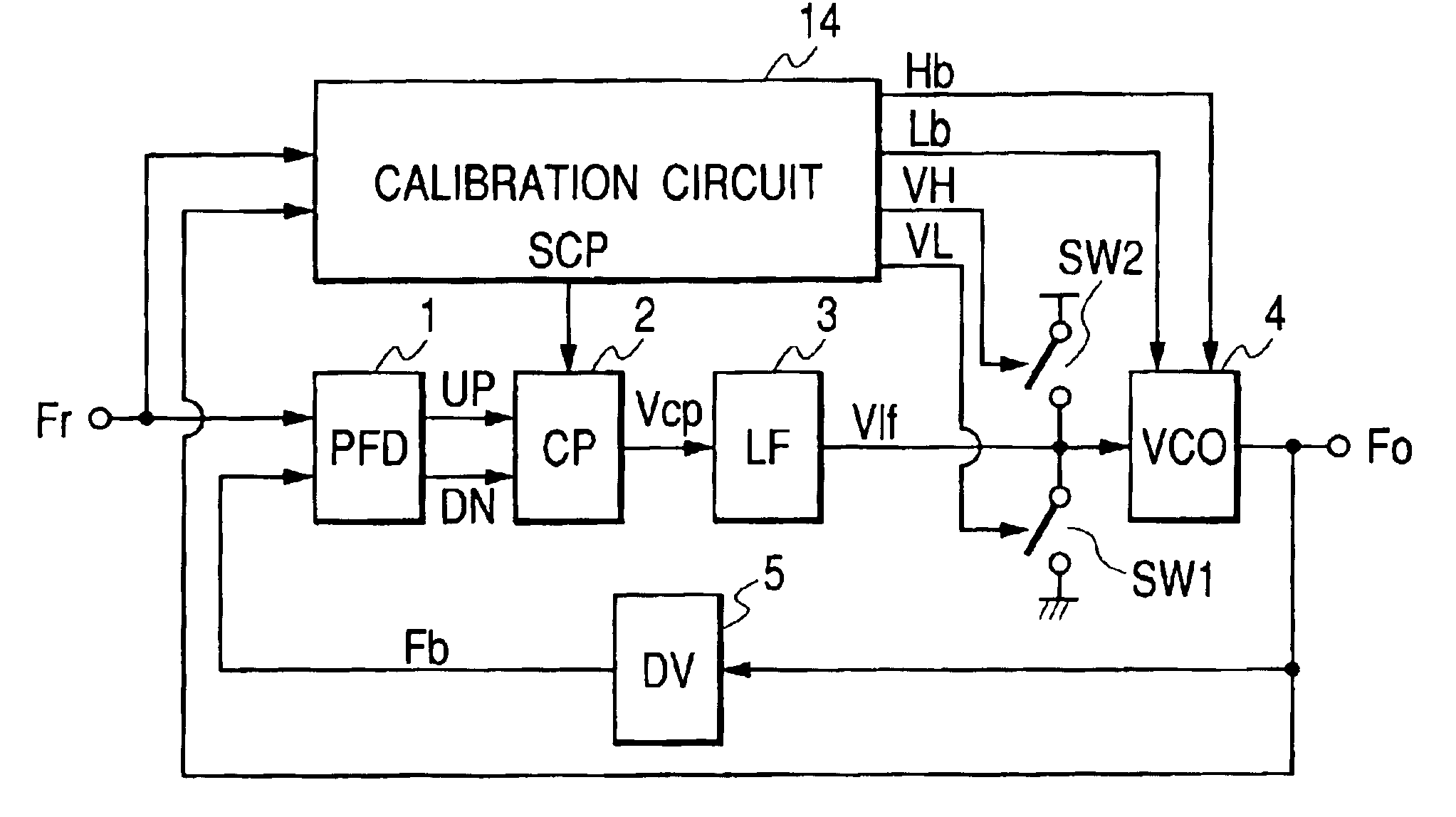
[0049]The configuration of the PSC according to embodiment is shown in FIG. 5. The PSC of this embodiment is composed of a PLL consisting of the phase comparator (PFD) 1, the charge pump (CP) 2, the loop filter (LP) 3, the voltage controlled oscillator (VCO) 4, and the divider (DV) 5, and a calibration circuit 14 for automatically adjusting the oscillation frequency ranges of the VCO 4.

[0050]The PSC of this embodiment operates under two operation s...


PUM


Abstract

An object of this invention is to provide a phase synchronizing circuit capable of automatically adjusting a VCO such that the VCO satisfies a predetermined frequency range even in a frequency range in which the VCO oscillates by a leak current generated if a low threshold process is applied. The phase synchronizing circuit is composed of a PLL consisting of a phase comparator, a charge pump, a loop filter, a VCO, and a divider, and a calibration circuit for automatically adjusting a frequency range of the VCO. Before a convergence operation is started, a switch is closed in response to a signal Rst of the calibration circuit such that an output of the loop filter is leveled to the ground and the PLL is set to be an open loop. A VCO output Fo is set at an upper limit frequency or a lower limit frequency in response to a Vcal signal, and its frequency is measured by comparing its period with a period of a reference signal Fr, and signals Hb, Lb used for adjusting the frequency of the VCO are updated. The signals Hb, Lb are updated until the VCO satisfies the predetermined frequency range, and subsequently their values are maintained. The switch opens in response to the signal Rst, and the PLL is changed over to a close loop to start phase synchronization.

Description

FIELD OF THE INVENTION[0002]The present invention relates to a phase synchronizing circuit and more particularly to a phase synchronizing circuit having a variable frequency oscillation circuit whose frequency tuning range can be automatically set in a predetermined range.BACKGROUND OF THE INVENTION[0003]A phase synchronizing circuit comprising a phase locked loop (PLL) is often used for generating a high-speed clock inside a logic LSI, adjusting phase with a RAM module connected to the outside of an LSI. The circuit configuration of the PLL is stated in detail, for example, in “A PLL Clock Generator with 5 to 110 MHz of Lock Range for Microprocessor” by I. Young (IEEE Journal of Solid-state Circuits, Vol. SC-27, pp. 1599-1607, November 1992) etc.[0004]The basic configuration of the PLL is shown in FIG. 1. The PLL is composed of a phase comparator (PFD) 1, a charge pump (CP) 2, a loop filter (LF) 3, a voltage controlled oscillator (VCO) 4, and a divider (DV) 5. The phase comparator ...

Claims


Application Information

Patent Timeline
Patent Type & Authority Patents(United States)
IPC IPC(8): H03L7/113H03L7/089H03L7/099H03L7/18H03L7/08H03L7/16
CPCH03L7/0891H03L7/18H03L7/113H03L7/0995
Inventor SHIBAHARA, YOSHIYUKIKOKUBO, MASARU
Owner RENESAS ELECTRONICS CORP
Why Eureka
Try Eureka