Portable spectral imaging microscope system

a spectroscopic imaging and microscope technology, applied in the field of portable spectroscopic imaging microscopes, can solve the problems of not being able to use such conventional spectral microscope systems, not being able to collect single or multiple spectra from precisely identified locations within samples, and not being able to disclose any mechanism for accurately positioning the probe head

Inactive Publication Date: 2005-03-22
PERKY PET PRODS
View PDF13 Cites 16 Cited by
  • Summary
  • Abstract
  • Description
  • Claims
  • Application Information

AI Technical Summary

Benefits of technology

A further feature of spectroscopic microscope of the present invention is that it can be used any angle and brought to a stationary sample rather than requiring that the sample be set on a translation stage for alignment to a fixed microscope objective. Furthermore, when implemented using a collection fiber bundle containing multiple optical fibers (and an imaging spectrograph with sufficient resolution to separately view each fiber), a spectroscopic microscope of the present invention can be used to simultaneously collect multiple spectra, each originating from a different precisely defined ...

Problems solved by technology

For some applications, such as samples in a vacuum chamber, in an oven, or located in a manufacturing process, one cannot use such conventional spectral microscope systems.
U.S. Pat. No. 6,115,528 discloses a fiber optic based probe assembly for use in hostile environments, but the probe heads do not allow the sample to be directly viewed and thus do not allow the collection of either a single or multiple spectra from precisely identified locations within a sample, as visually viewed through the same objective lens us...

Method used


Image

  • Portable spectral imaging microscope system
  • Portable spectral imaging microscope system
  • Portable spectral imaging microscope system

Examples


Embodiment Construction

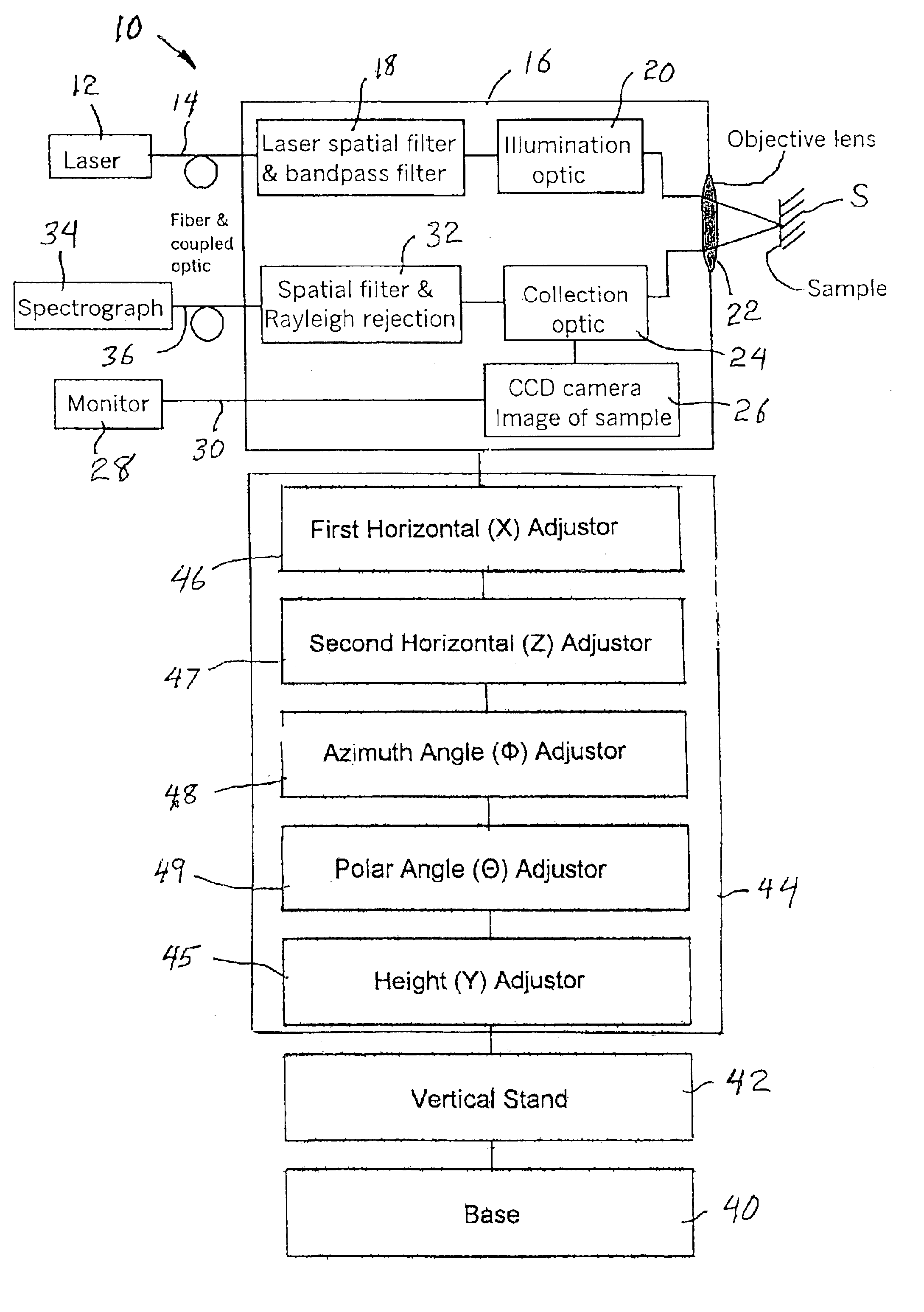
A portable spectroscopic imaging microscope system 10 of the present invention is shown in block diagram form in FIG. 1. The system 10 includes a laser 12 coupled by a fiber optic cable 14 to a probe head 16. The probe head 16 includes filter elements 18 and optical path defining elements 20 that direct energy from the fiber optic cable 14 to an objective lens 22 to illuminate a specimen or sample S. The probe head also includes collection optical path defining elements 24 that are arranged to intercept any desired spectral signal reflected, scattered or emitted by the illuminated sample S passing back through the objective lens 22. The collection optic elements 24 direct a portion of the reflected, scattered or emitted signal to a CCD camera 26 to form a visual image signal of the sample S. The visual image signal is transmitted to a monitor 28 by way of a suitable cable 30. The collection optics 24 also direct a portion of the reflected, scattered or emitted signal to filter eleme...


PUM


Abstract

A portable spectral imaging microscope includes a probe head coupled via fiber optic cabling to a laser source and to a spectrograph. The probe head is coupled to a position controller that is mounted on a base suitable for positioning adjacent to a sample. The position controller has five degrees of freedom that permits one to adjust the position and direction of the probe head relative to the sample over a wide range of dimensions and angles. The entire probe head can be easily moved in order to precisely align the objective lens to stationary samples for simultaneous viewing and spectral analysis.

Description

BACKGROUND OF THE INVENTION1. Field of the InventionThe present invention generally relates to portable spectroscopic imaging microscopes, including portable Raman imaging microscope systems and portable fluorescence imaging microscope systems.2. Description of Prior ArtConventional spectral microscope systems allow a sample to be viewed through a video camera or an eyepiece. However, the sample must generally be fixed on a movable stage or table of the microscope and moved toward or away from the objective lens to achieve proper focus as disclosed, for example, in U.S. Pat. Nos. 5,194,912; 5,442,438; 5,479,252; 6,002,476 and 6,069,690. For some applications, such as samples in a vacuum chamber, in an oven, or located in a manufacturing process, one cannot use such conventional spectral microscope systems. U.S. Pat. No. 6,008,894 discloses a Raman spectroscopy probe for analyzing specimens in adverse environments requiring remote focusing of the probe, and suggests mounting the prob...

Claims


Application Information

Patent Timeline
IPC IPC(8): G01N21/65G01N21/63G02B21/24
CPCG01N21/65G02B21/241G01N21/6458G01N2201/0221G01N2021/656
Inventor JIANG, YANAN
Owner PERKY PET PRODS
Why Eureka
Try Eureka