
System and method for transfer of IP data in an optical communication networks

a technology of optical communication network and ip data, applied in data switching network, transmission monitoring, multiplex communication, etc., can solve the problems of inefficiency in system operation, waste associated with the operation, and inability to fully utilize the payload bytes, so as to reduce the complexity of outstations and remove the burden of high cost and complexity

Inactive Publication Date: 2005-03-22
RPX CLEARINGHOUSE
View PDF8 Cites 60 Cited by
  • Summary
  • Abstract
  • Description
  • Claims
  • Application Information

AI Technical Summary

Benefits of technology

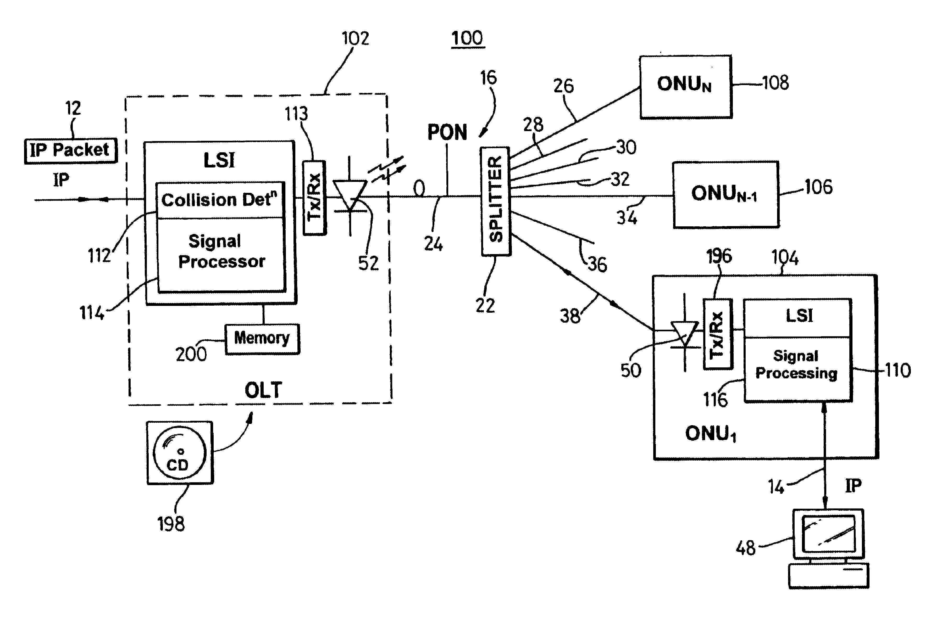
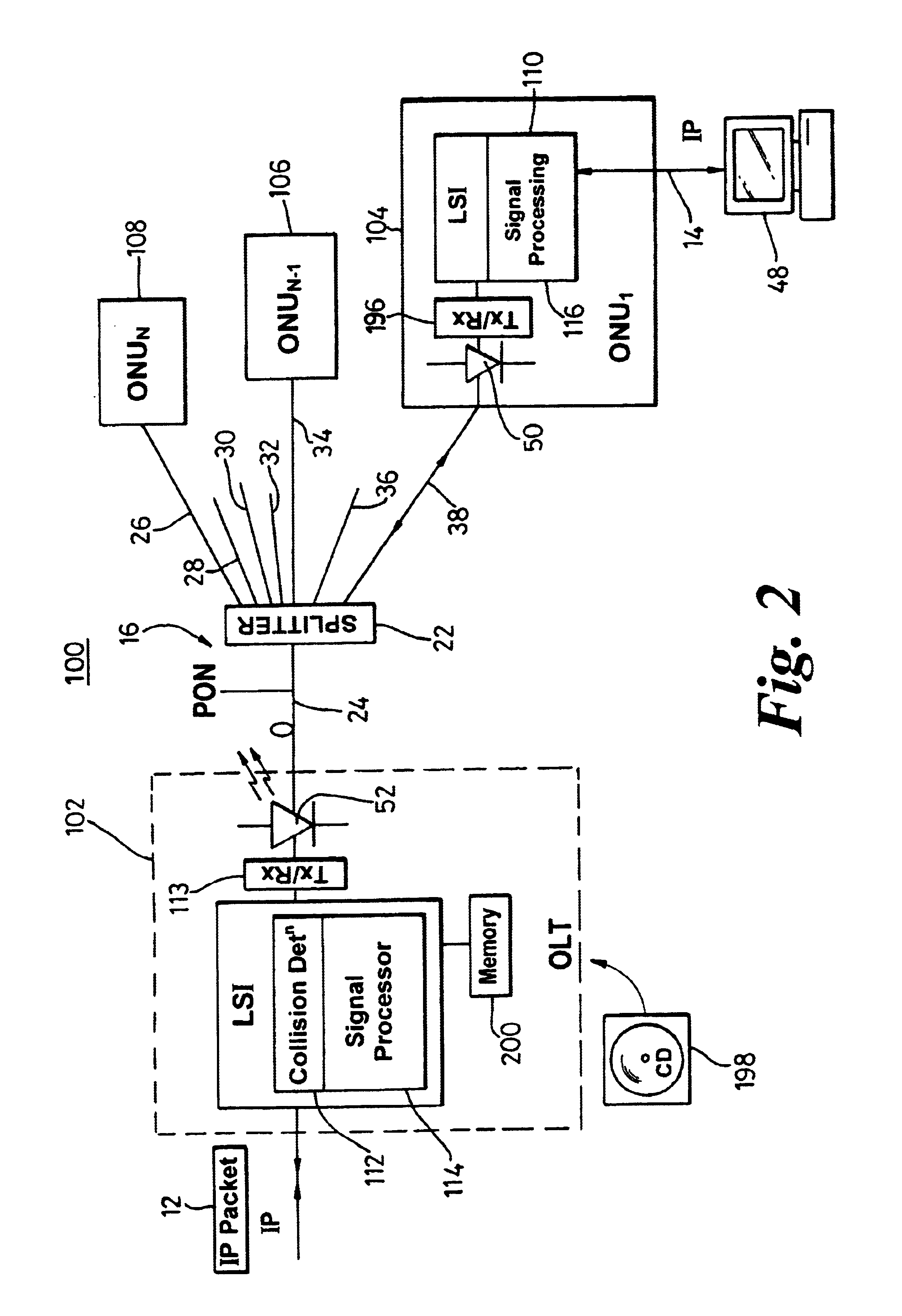
Advantageously, the present invention provides a point-to-multipoint optical transmission system which enables the transfer of IP traffic in its native format over a PON. The IP PON ensures secure, independent connections from each user to the exchange and robust transport over the fibre network. A simple IP transport protocol is used which removes the need for complex and expensive APON LSI chips in each outstation. The present invention therefore, beneficially, reduces the complexity of outstations by removing the burdens of the high cost and complexity associated with locating an APON LSI or collision detection unit at each outstation.

Problems solved by technology

However, with any packet-based system, under-utilisation of the payload bytes is always a possibility.
Clearly, under-utilisation leads to inefficiencies within system operation and, specifically, an associated waste (arising from an effective requirement of pre-allocation) of, ultimately, limited bandwidth (even with the use of dedicated ATM adaptation layer (AAL) protocols).
Consequently, an APON LSI component is both complex and expensive.
Protocol conversion (i.e. ATM adaptation) from, say, an IP to an ATM domain is processor intensive, time consuming and also expensive.
More specifically, the serial interconnection plan curtails communication at any break in the central bus and so network access may be restricted in a partially operational system.
In any event, within such Ethernet systems, every outstation coupled to a common bus potentially has access to the data addressed to or emanating from every other interconnected outstation, and so the network is somewhat unsecure in the sense that an unscrupulous user could illicitly look to recover / monitor data traffic.
Optical networks are therefore now supporting IP to broadband ATM conversion, and this imposes a cost implication (both financial and operational performance-related) principally on subscriber units, such as outstations.
This system therefore suffers from a decreased level of security compared to APON since all uplink transmissions may be seen by all ONUs, although this can be overcome by providing encryption either at each ONU.
In any event, there is still a possibility that uplink data collisions can occur, since instantaneously commenced transmissions from multiple ONUs will not be detected by any collision detection algorithm.
From a telecommunications operator's perspective, it is normally desirable that access networks intended for linking individual customers to a central facility should provide connectivity between any customer and the central facility, but should not allow traffic to pass directly from customer to customer since this may inhibit the operator's ability to bill the customer for the service, in addition to privacy implications discussed above.

Method used


Image

  • System and method for transfer of IP data in an optical communication networks
  • System and method for transfer of IP data in an optical communication networks
  • System and method for transfer of IP data in an optical communication networks

Examples


Embodiment Construction

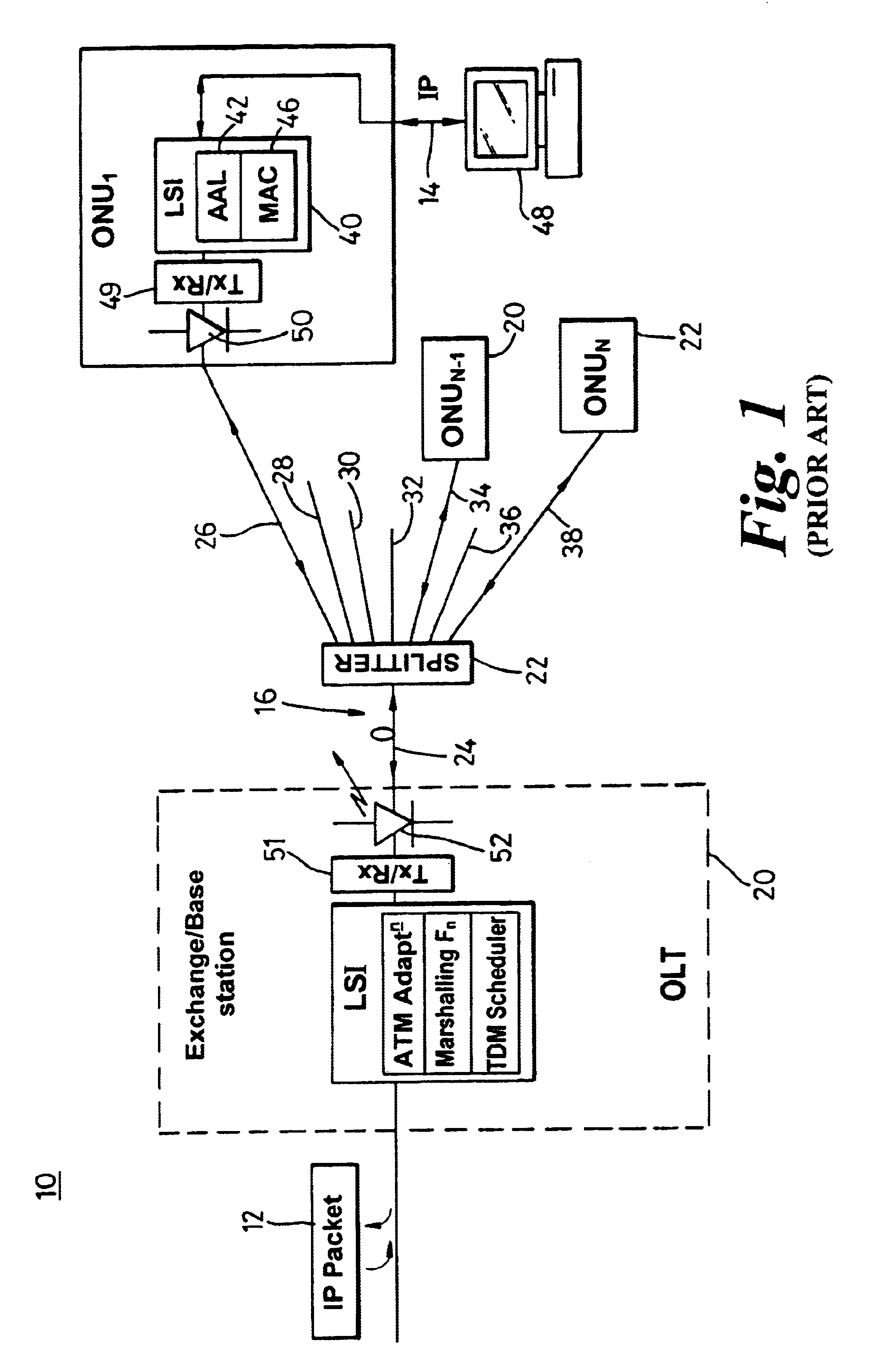
FIG. 1 illustrates a prior art duplex optical communication network 10 in which data 12-14 is transferred across a PON 16 using ATM as the transport protocol. In such APONs, outstations 1822 (of which only three are shown for clarity reasons) may only transmit data when specifically allowed to do so by instructions from a base station or exchange, generally termed “optical line termination equipment” (OLT) 20. The OLT 20, located at the ‘headend’ of the network 10, is connected to a passive optical splitter 22 via an optical fibre 24. A passive splitter 22 is used to distribute (in the downlink) and consolidate (in the uplink) signals to and from the OLT to and from several ONUs. The passive splitter therefore includes a single fibre 24 interface and a multiple fibre 26-38 interface, i.e. point-to-multipoint connectivity. Each of the multiplicity of outgoing fibres 26-38 terminates at one of the outstations, which outstations each contain an LSI chip 40 and to other circuitry (appre...


PUM


Abstract

A system (100) to enable the transfer of Internet protocol (IP) format data (12, 14) over a point-to-multipoint passive optical network (PON, 16) is illustrated in FIG. 2. An exchange (102) is connected to a plurality of outstations (104-108) via an optical communication resource (24, 26-38) including a passive optical splitter (22) providing isolation to individual outstations. Media access control of the plurality of outstations is administered by the exchange (102), with collision detection logic (112) in the exchange determining collision (158) of Internet protocol (IP) encoded data communicated thereto through the PON (16). The IP encoded data realises a transport mechanism through the PON. Each of the plurality of outstations (104-108) and the exchange (102) is adapted to pass data in an IP format to and from the optical communication resource such that IP encoded data is transported, in use, directly between the outstation and the exchange.

Description

BACKGROUND TO THE INVENTIONThis invention relates, in general, to a system and method for transporting data, video and voice traffic between an exchange and a user within an optical communication network and is particularly, but not exclusively, applicable to the transfer of internet protocol (IP) traffic (in its native form) over a passive optical network (PON).SUMMARY OF THE PRIOR ARTModern telecommunications systems are increasingly carrying data in an optical transfer domain between exchanges and end-users via optical fibre, thereby conveying data in a fast, reliable and accurate way. A passive optical network (PON) refers to a system in which the transported optical signal is not converted or amplified in any significant way. PONs consequently provide a simple and cheap method of transferring data between an exchange and a variety of end-users, including domestic dwellings and small businesses since little can go wrong within passive elements and active devices otherwise avoide...

Claims


Application Information

Patent Timeline
Patent Type & Authority Patents(United States)
IPC IPC(8): H04J14/08H04Q11/00H04J14/02H04L12/413
CPCH04J14/0226H04J14/0283H04L12/403H04L12/413H04J14/0252H04Q11/0067H04J14/0232H04J14/0247H04Q2011/0064H04Q11/0066
Inventor DYKE, PETERDYER, MICHAEL P
Owner RPX CLEARINGHOUSE
Learn More