Raman amplifier system

a technology of amplifier system and amplifier, which is applied in the field oframan amplifier system, can solve the problems of limited effect noise factor of raman amplifier arrangement, which can be obtained, and additionally reduced optical signal-to-noise ratio (osnr) of optical data signal, so as to achieve less strong attenuation, improved effect noise factor of raman amplifier system, and high effective cross-section

Inactive Publication Date: 2005-03-22
XIEON NETWORKS SARL
View PDF4 Cites 6 Cited by
  • Summary
  • Abstract
  • Description
  • Claims
  • Application Information

AI Technical Summary

Benefits of technology

A key aspect of the inventive Raman amplifier arrangement is that a series circuit is provided as an optical transmission medium, whereby the series circuit is composed of a standard single-mode fiber, which is arranged on the transmit side, of a first optical fiber and of a second optical fiber, which is arranged on the receive side, whereby an optical pump signal is launched into the second optical fiber on the receive side in order to generate the Raman effect in the first optical fiber and the first optical fiber has an effective fiber cross-section of less than 60 μm2 and a nonlinearity constant of more than 1*101 1/W and the second optical fiber has an effective fiber cross-section of more than 100 μm2 and a nonlinearity constant of less than 1*10−8 1/W. As a result of the inventively high effective cross-section of more than 100 μm2 and the low nonlinearity constant of less than 1*10−8 1/W of the second optical fiber, the optical pump light, with a relative

Problems solved by technology

Furthermore, the effective noise factor of the Raman amplifier arrangement, which can be obtained, is limited given the use of Raman pump capacities of less than 1 Watt, see Govind

Method used


Image

  • Raman amplifier system
  • Raman amplifier system

Examples


Embodiment Construction

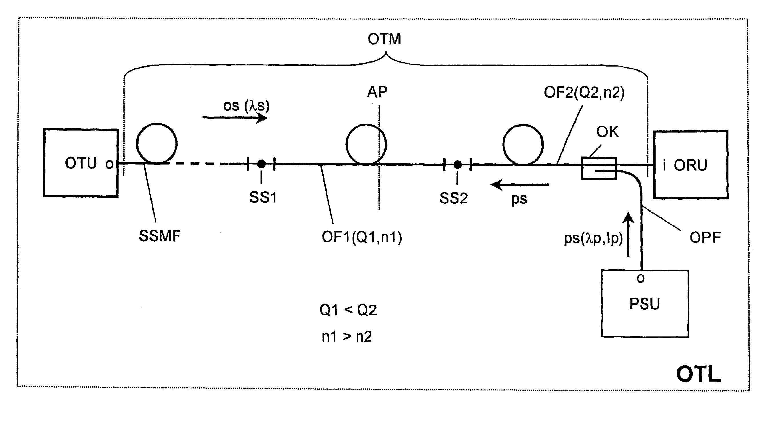
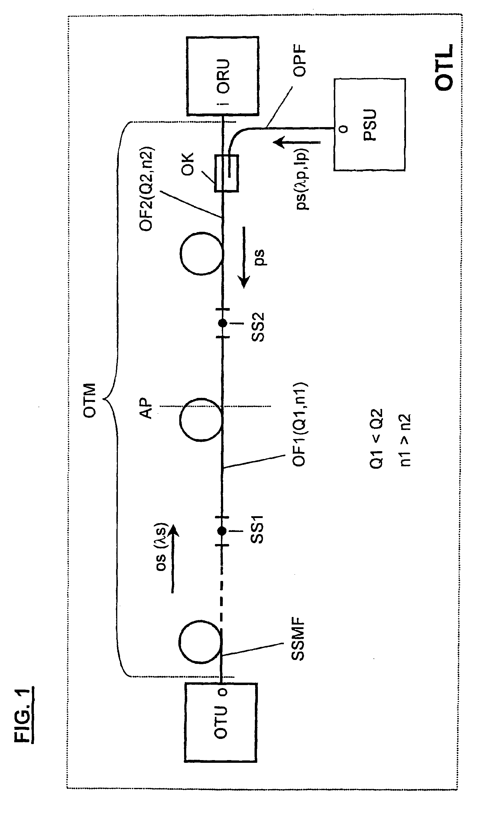
For example, FIG. 1 shows an optical transmission path OTL having an optical transmission unit OTU and an optical reception unit ORU, whereby an output o of the optical transmission unit OTU, via an optical standard single-mode fiber SSMF, a first optical fiber OF1 and second optical fiber OF2 and an optical coupler OK, is connected to an input i of the optical reception unit ORU. FIG. 1 refers to the transmission locations between the optical standard single-mode fiber SSMF and the first optical fiber OF1 or, respectively, between the first optical fiber OF1 and the second optical fiber OF2 as a first splice location SS1 or, respectively, second splice location SS2. Furthermore, the optical coupler OK, via an optical pump fiber OPF, is connected to a pump signal unit PSU having an output o. The optical transmission medium OTM is inventively composed of a series circuit of the optical standard single-mode fiber SSMF, the first optical fiber OF1, and the second optical fiber OF2.

The ...


PUM


Abstract

A Raman amplifier system is provided for amplifying optical signals that are transmitted via a transmission medium, the series circuit being composed of a standard single-mode fiber arranged on a transmit side, and a second optical fiber arranged on a receive side.

Description

BACKGROUND OF THE INVENTIONThe present invention is directed to a Raman amplifier system for amplifying optical signals that are transmitted via a transmission medium.In present and future optical transmission systems, particularly with respect to transmission systems operating according to the WDM principle (Wavelength Division Multiplexing), a pump wave inserts optical pump signals into an optical standard single-mode fiber in order to provide the necessary optical pump power for optical amplifiers preceding the launching location; for example, erbium amplifiers. Furthermore, such optical pump signals are used for directly amplifying optical signals to be transmitted, whereby the optical amplification caused by the optical pump signals is based on the Raman effect. For example, the Raman effect (“Stimulated Raman Scattering”) is described in “Nonlinear Fiber Optics” by Govind P. Agrawal, Academic Press, 1995, see pages 316 to 322.The Raman preamplifier is known as a specific embod...

Claims


Application Information

Patent Timeline
IPC IPC(8): H04B10/17G02F1/35H01S3/07H01S3/10H01S3/30H04B10/291
CPCH04B10/2916
Inventor CREMER, CORNELIUS
Owner XIEON NETWORKS SARL
Why Eureka
Try Eureka