
Circuit configuration for controlling the transmitting power of a battery-operated transceiver

a transceiver and circuit configuration technology, applied in power management, process and machine control, instruments, etc., can solve the problem of delay in the switching off of the device, and achieve the effect of longer operation tim

Inactive Publication Date: 2005-03-22
INTEL CORP
View PDF14 Cites 20 Cited by
  • Summary
  • Abstract
  • Description
  • Claims
  • Application Information

AI Technical Summary

Benefits of technology

[0007]It is accordingly an object of the invention to provide a circuit configuration for controlling the transmitting power of a battery-operated transceiver, which overcomes the hereinafore-mentioned disadvantages of the heretofore-known devices of this general type so that operating time is longer.
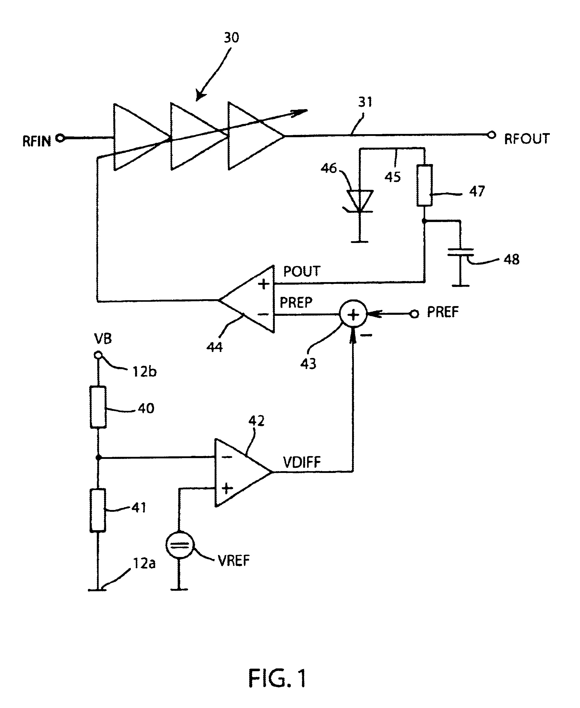
[0009]In a circuit configuration according to the invention, the transmitting power of the transceiver is reduced in dependence on the battery voltage. For this purpose, the nominal value of the power control is lowered in dependence on the battery voltage. If a telephone call is made at the end of the battery charge in a mobile transceiver having such a circuit configuration, the availability of the battery is extended due to two effects. On one hand, the availability is extended due to the reduced power consumption so that less current is drawn from the battery and, as a result, sufficient battery charge is available longer with a given capacity. On the other hand, the availability is extended due to the reduced voltage drop across the internal impedance of the battery due to the lower load current so that the switching-off of the device is delayed.

Problems solved by technology

On the other hand, the availability is extended due to the reduced voltage drop across the internal impedance of the battery due to the lower load current so that the switching-off of the device is delayed.

Method used


Image

  • Circuit configuration for controlling the transmitting power of a battery-operated transceiver
  • Circuit configuration for controlling the transmitting power of a battery-operated transceiver
  • Circuit configuration for controlling the transmitting power of a battery-operated transceiver

Examples


Embodiment Construction

WINGS

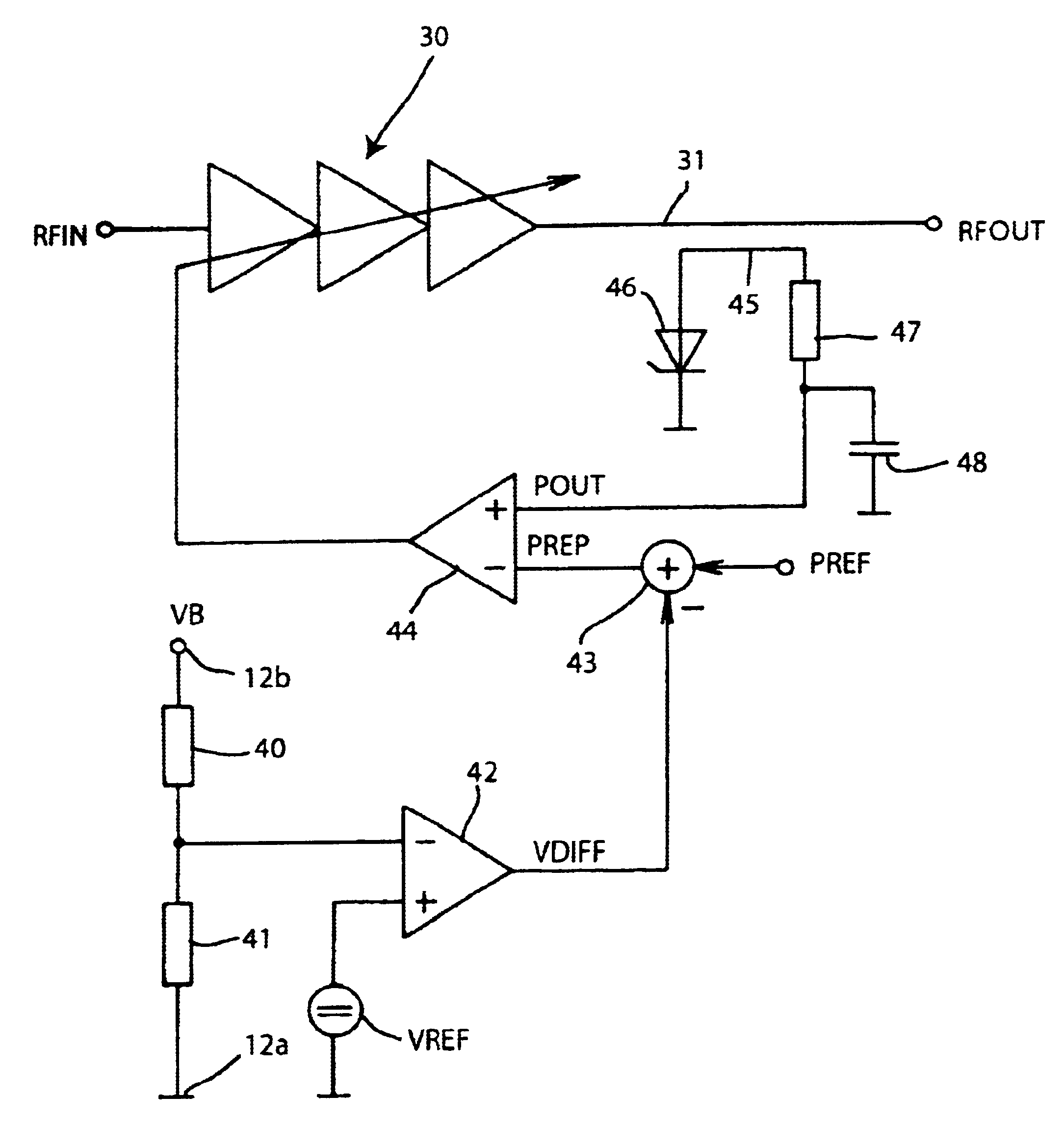
[0015]FIG. 1 is a schematic diagram of a circuit configuration according to the invention;

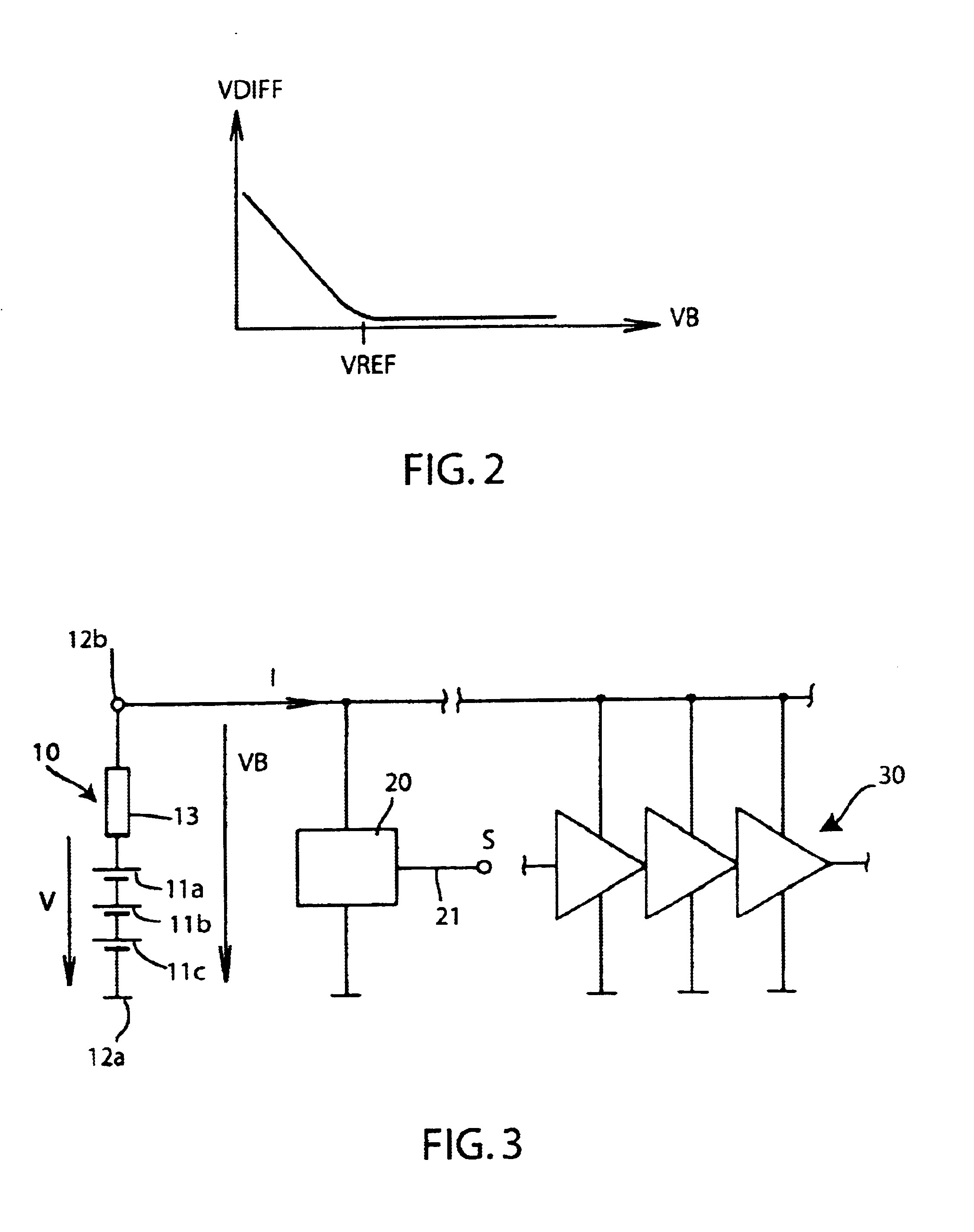
[0016]FIG. 2 is a graph showing a characteristic of a comparator of the circuit of FIG. 1; and

[0017]FIG. 3 is a basic schematic and block diagram of a battery of a mobile transceiver with connected loads.

DESCRIPTION OF THE PREFERRED EMBODIMENTS

[0018]Referring now to the figures of the drawings in detail and first, particularly, to FIG. 3 thereof, there is seen a circuit having a battery 10 which includes three battery cells 11a, 11b and 11c that are connected in series. A voltage V is impressed by the three battery cells 11a, 11b, 11c. The voltage V drops as the discharging of the battery increases. The battery cells 11a, 11b and 11c are connected in series inside the battery with an internal impedance 13. An operating voltage VB which supplies the mobile transceiver is present at terminals 12a and 12b. A correspondingly high voltage is dropped across the internal impedance 13 depending on...


PUM


Abstract

A circuit configuration is provided for controlling the transmitting power of a battery-operated transceiver. A high transmitting power of a mobile transceiver generates a high voltage drop across an internal impedance of the battery which can lead to the device switching off. A reduction in the transmitting power in dependence on the battery voltage is therefore proposed. The battery voltage is thus compared with a reference voltage and a signal representing a nominal transmitting power is correspondingly corrected. The circuit can be integrated in a simple manner with analog components in an IC.

Description

BACKGROUND OF THE INVENTION[0002]Field of the Invention[0003]The invention relates to a circuit configuration for controlling the transmitting power of a battery-operated transceiver having a battery for providing a supply voltage and a power stage for the controllable amplification of a radio-frequency signal.[0004]Mobile transceivers, especially cellular digital mobile telephones, are supplied with voltage by a battery. The higher the transmitting power of the mobile telephone, the higher the current drawn from the battery. The current flowing through the battery produces a voltage drop across its internal impedance. When the current is higher, the voltage provided for the circuit to be supplied correspondingly drops. That loaded voltage is therefore lower than an idling voltage. If the operating voltage supplied by the battery is no longer sufficient for proper operation of the mobile transceiver, the device is switched off.[0005]In mobile telephones, a power output stage generat...

Claims


Application Information

Patent Timeline
IPC IPC(8): H04B1/16H04B7/005H04B1/04H03G3/00
CPCH03G3/007H04B1/04H04W52/30H04W52/28H04B2001/0416
Inventor WAHL, MARTIN
Owner INTEL CORP
Learn More