Self-modulating inert gas fire suppression system

a fire suppression system and self-modulation technology, applied in the direction of instruments, pressure relieving devices on sealing faces, container discharging methods, etc., can solve the problems of high initial gas flow rate and rapid decline to a very low gas flow rate, and achieve the effect of constant flow ra

Inactive Publication Date: 2005-03-29
FIKE CORP
View PDF29 Cites 51 Cited by
  • Summary
  • Abstract
  • Description
  • Claims
  • Application Information

AI Technical Summary

Benefits of technology

The present invention overcomes the problems outlined above and provides an improved hazard suppression system capable of effectively suppressing hazards such as fire through use of relatively low pressure inert gas cylinders together with specially designed cylinder-mounted discharge valves capable of delivering the gas at generally constant pressure levels throughout a majority of the time of gas delivery. In this way, use can be made of existing piping systems designed for Halon suppressants, or in the case of new systems less expensive piping and distribution hardware may be employed.
The gas pressure within the cylinders, which is stored nominally at 300 bar, is released through a respective modulating valve at a constant pressure of about 20 to 50 bar at a relatively constant flow rate. Notwithstanding this relatively low controlled release pressure and flow rate, the systems of the invention are capable of supplying adequate suppression gas to the protected area within established time constraints. This represents a significant economic advantage.

Problems solved by technology

In prior high-pressure inert gas systems employing a high-pressure letdown orifice plate, release of gas from the storage cylinders for discharge from the manifold pipe through the orifice plate resulted in very high initial gas flow rates, which declined rapidly to a very low gas flow rate.

Method used


Image

  • Self-modulating inert gas fire suppression system
  • Self-modulating inert gas fire suppression system
  • Self-modulating inert gas fire suppression system

Examples


Embodiment Construction

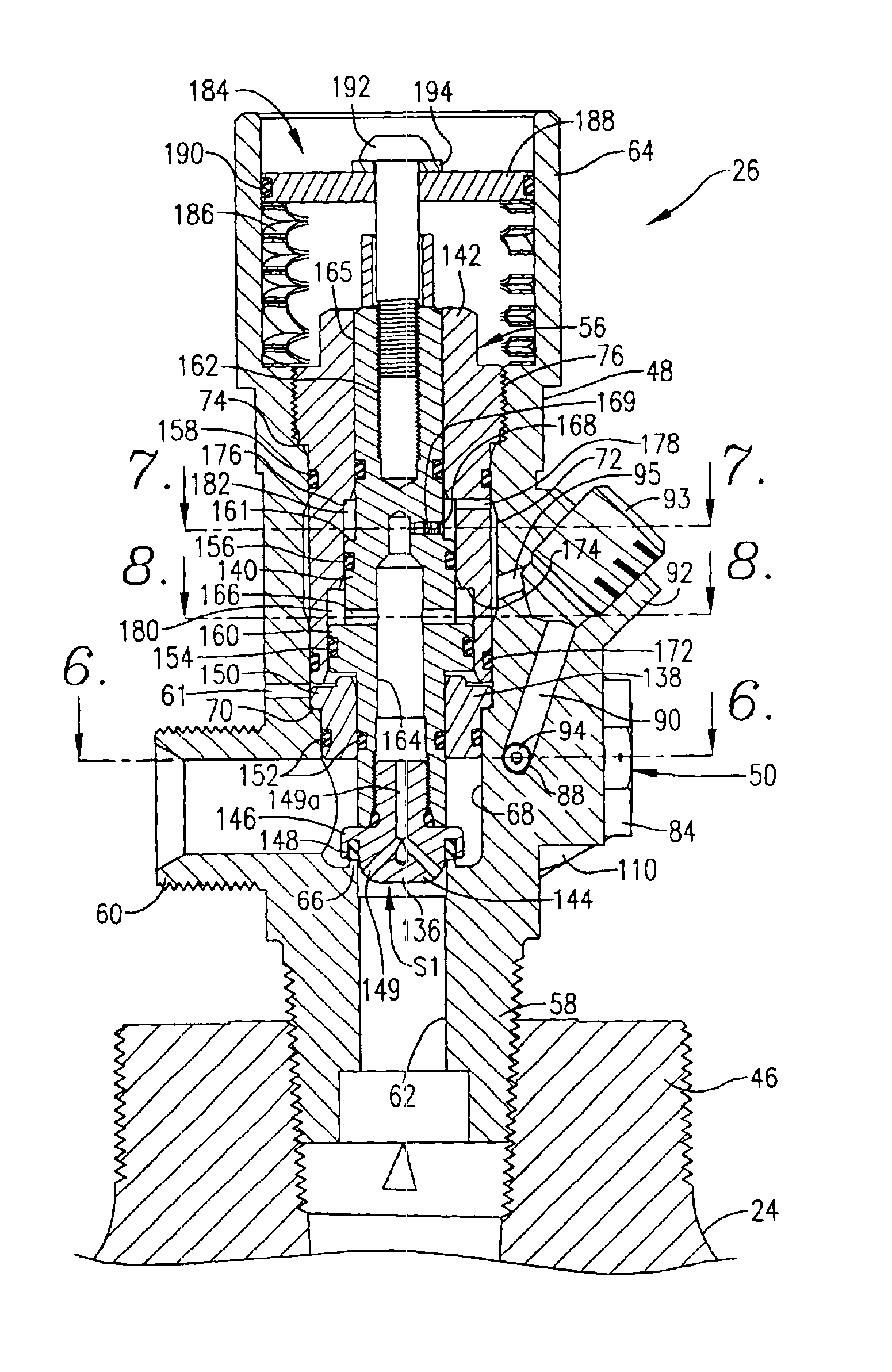
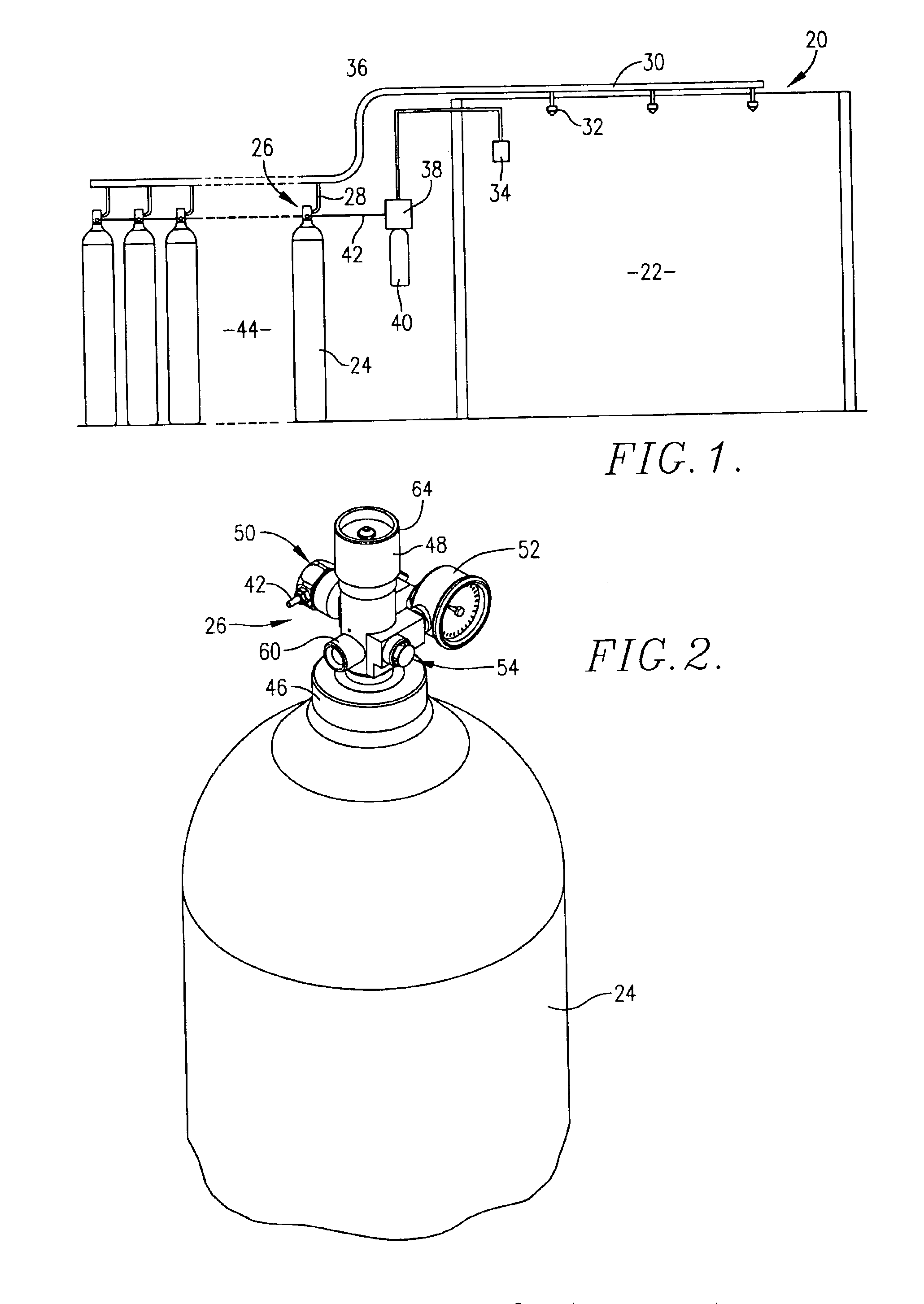
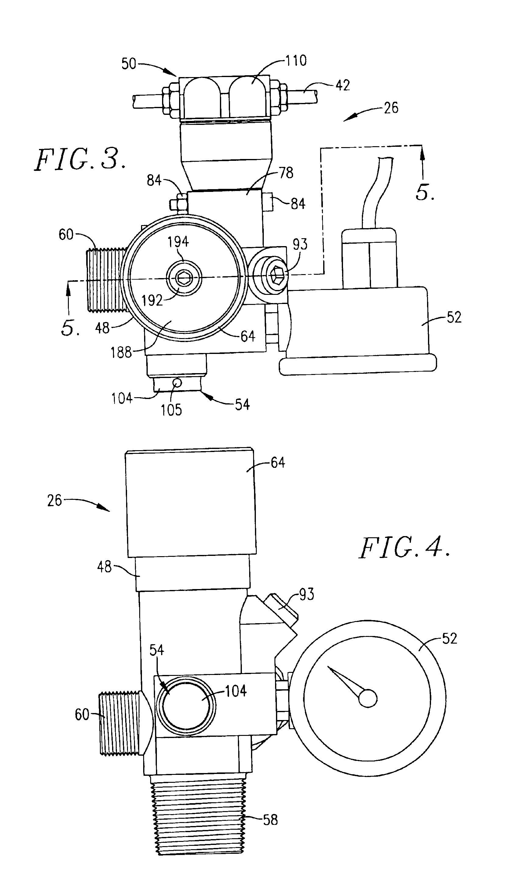
Turning now the drawings, a hazard suppression system 20 is schematically illustrated in FIG. 1. The system 20 is designed to protect an enclosed room 22 which may house computer equipment or other valuable components. Broadly speaking, the system 20 includes a plurality of high-pressure inert gas cylinders 24 each equipped with a valve unit 26. Each valve unit 26 is connected via a conduit 28 to a manifold assembly 30. As illustrated, the assembly 30 extends into room 22 and is equipped with a plurality of nozzles 32 for delivery of inert gas into the room 22 for hazard suppression purposes. The piping making up the system 30 may be conventional schedule 40 pipe as opposed to the heavy-duty schedule 160 manifold piping and pressure letdown orifice plate required of prior systems of this character. The overall system 20 further includes a hazard detector 34 which is coupled by means of an electrical cable 36 to a solenoid valve 38. The latter is operatively connected to a small cyli...


PUM


Abstract

A relatively low pressure inert gas hazard suppression system (20) is provided which is designed to protect a room (22) or the like from the effects of fire or other hazard. The system (20) includes a plurality of pressurized inert gas cylinders (24) each equipped with a valve unit (26); each valve unit (26) is in turn coupled via a conduit (28) to a delivery manifold (30). The respective valve units (26) are operable to deliver gas from the cylinders (24) at a generally constant pressure (usually around 10-100 bar) throughout a substantial portion of the time of gas delivery, to thereby provide effective hazard suppression without the need for expensive high-pressure gas handling and distribution hardware and a reduction in room venting area due to lower room over-pressurization. Each valve unit (26) has a valve body (48) and a shiftable piston-type sealing member (56). Gas pressure from the cylinder (24) and a spring assembly (184) biases the member 56 to the valve open position, this being counterbalanced by gas pressure within equalization and modulation chambers (180, 182) provided in the valve unit (26). When a hazard is detected, the valve units (26) are actuated by draining of gas from the modulation chambers (182), allowing gas flow from the cylinders (24). As gas discharge proceeds, gas flows into and out of the modulation chambers (182) so as to achieve the desired generally constant pressure gas output. Near the end of gas discharge, the spring assembly (184) becomes predominant and holds the valve unit (26) open until all gas is discharged.

Description

BACKGROUND OF THE INVENTION1. Field of the InventionThe present invention relates to inert gas hazard suppression assemblies used to protect areas or rooms such as computer equipment rooms from hazards, and especially fire. More particularly, the invention relates to such systems, as well as pressure modulating inert gas valves forming a part thereof, where multiple high-pressure inert gas cylinders are used, with each cylinder having a valve unit operable to deliver relatively low pressure inert gas at a generally constant pressure throughout a significant period of time during which gas is delivered, thereby providing effective hazard suppression without the need for high-pressure gas handling and distribution equipment or pressure reducing orifice plates that are typical of prior inert gas hazard suppression systems. Each valve unit includes a spring assembly biasing the unit to an open, gas-flow position as well as a gas flow modulating circuit which maintains the gas pressure a...

Claims


Application Information

Patent Timeline
Patent Type & Authority Patents(United States)
IPC IPC(8): A62C8/00B05B1/30A62C35/68A62C99/00F17C13/04F17D3/00F17D5/00G08B
CPCF16K1/305F16K31/406F17C13/04A62C35/68F17C2270/0754F17C2201/0109F17C2201/032F17C2201/056F17C2201/058F17C2205/0326F17C2205/0385F17C2205/0394F17C2221/013F17C2221/014F17C2221/016F17C2223/0123F17C2223/036F17C2250/032F17C2250/036F17C2250/043F17C2250/0636F17C2270/05F17C2270/07A62C99/0018B05B1/30F17D3/00F17D5/00
Inventor STILWELL, BRADFORD T.KEITER, MICHAEL J.PATEL, DEVANG NARHARILALGOODALL, KEITH LESLIE
Owner FIKE CORP
Why Eureka
Try Eureka