System and method for biometric image capturing

Inactive Publication Date: 2005-03-29
CROSS MATCH TECH
View PDF21 Cites 14 Cited by
  • Summary
  • Abstract
  • Description
  • Claims
  • Application Information

AI Technical Summary

Benefits of technology

ct a high quality print image. One advantage of the present invention is that the platen may be cooled in these conditions to allow high quality print image to be detected.
On the other hand, heating the platen reduces or eliminates moisture and/or fluids around the area of the platen, where the biometric object is placed Such reduction or elimination of excess moisture surrounding the biometric object on the platen prevents a halo effect from appearing in the detected print image.
In embodiments of the invention, a controller controls each thermal element to cool or heat the platen. In one embodiment, a controller supplies current to the thermal assembly in order to increase or decrease the temperature of the thermal elements. A temperature sensor, attached to the controller detects temperature of the platen. If the temperature of the platen is above a certain threshold level, the temperature sensor sends a signal to the controller to supply current to the thermal assembly in order to increase the temperature of the platen. Increasing temperature of the platen will reduce or eliminate moisture and a resulting halo effect. If the temperature of the platen is below a certain thr

Problems solved by technology

This technique can be very messy due to the application of ink, and may often result in a set of prints that are difficult to read.
Excessive moisture and/or fluids on a finger, however, can be undesirable.
Excessive moisture and/or fluids may alt

Method used


Image

  • System and method for biometric image capturing
  • System and method for biometric image capturing
  • System and method for biometric image capturing

Examples


Example

The features, objects, and advantages of the present invention will become more apparent from the detailed description set forth below when taken in conjunction with the drawings in which like reference characters identify corresponding elements throughout. In the drawings, like reference numbers generally indicate identical, functionally similar, and / or structurally similar elements. The drawing in which an element first appears is indicated by the leftmost digit(s) in the corresponding reference number.

DETAILED DESCRIPTION OF THE INVENTION

Table of Contents

1. Introduction.2. Terminology.3. Temperature Controlled Biometric Scanner.4. Temperature Based Controller.

(A) Cooling.

(B) Heating.

(C) Automatic Control.5. Thermal Coupling.6. Method for Changing Temperature of the Platen.7. Conclusion.

1. Introduction

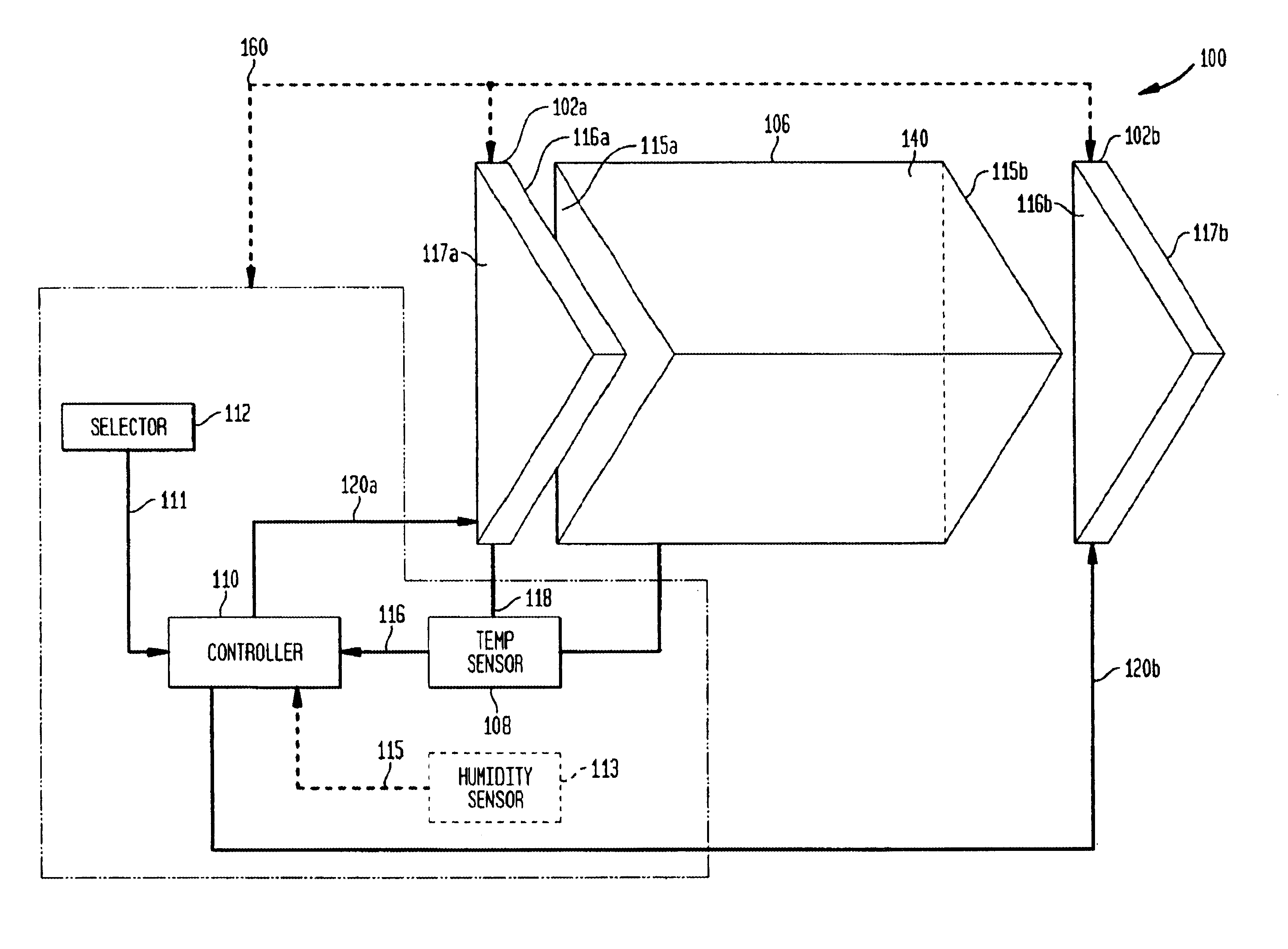
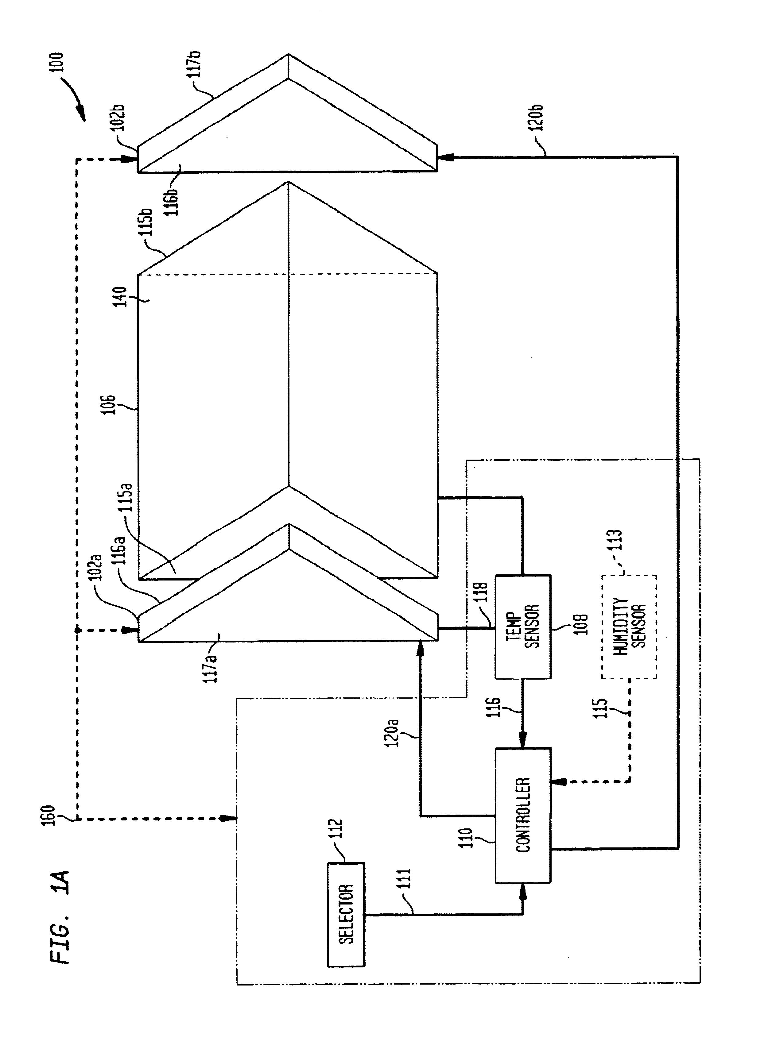
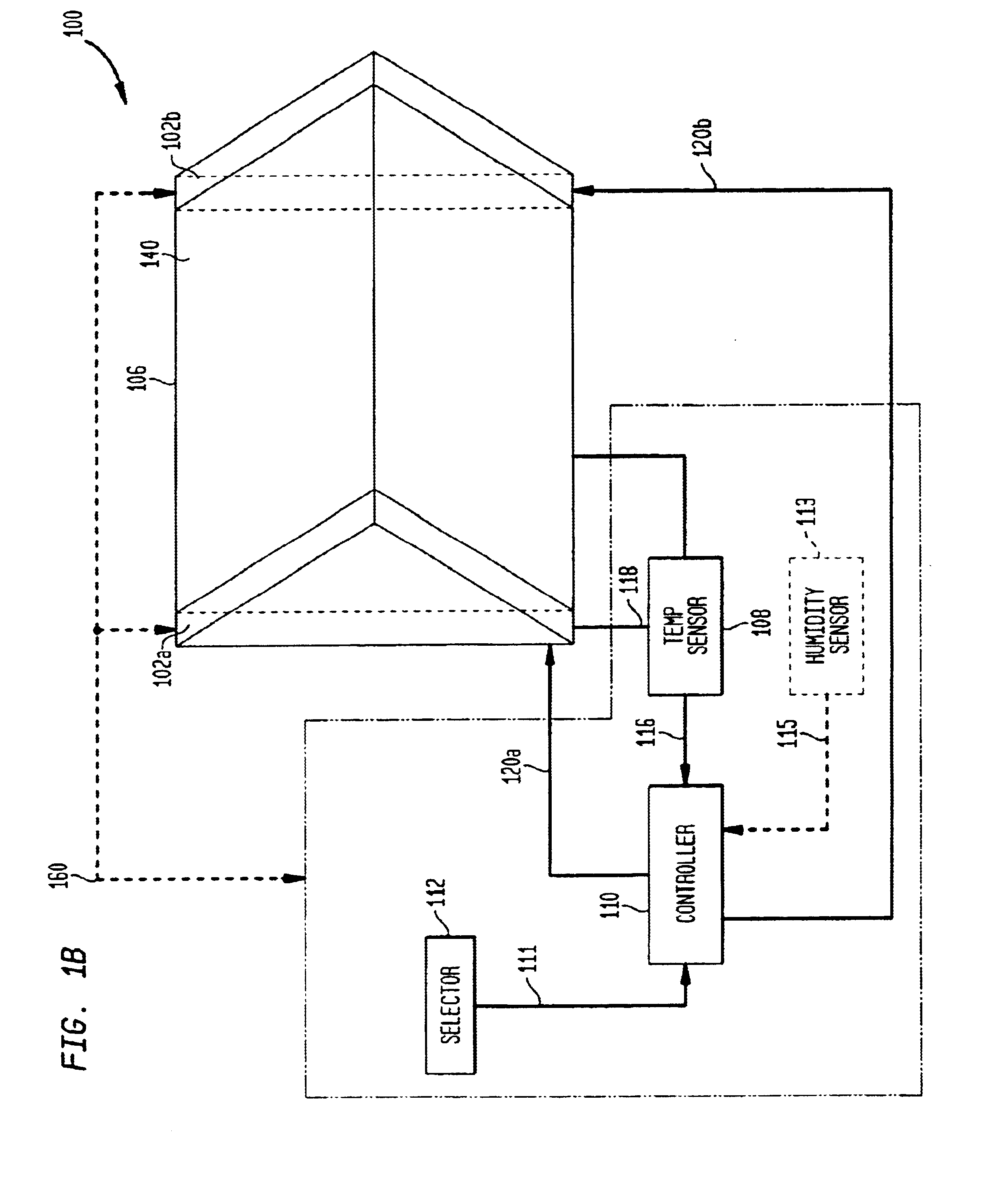
The present invention relates to systems and methods for capturing a biometric image using a live print scanning device. More specifically, the present invention relates to a live pr...


PUM


Abstract

Biometric object image capturing systems and methods prevent undesirable interruptions of total internal reflection of a prism that result in improper biometric images. A thermal assembly comprising a plurality of thermal elements is placed adjacent to the image capturing device. The thermal elements upon supply of a current are capable of either heating or cooling the image capturing device or a platen of the image capturing device. If cooling of the biometric object receiving surface is required, the thermal elements can be controlled to decrease temperature of an area where a biometric object is placed, or an area adjacent to where the biometric object is placed. If heating of the biometric object receiving surface is required, the thermal elements can be controlled to increase temperature of an area where a biometric object is placed, or an area adjacent to where the biometric object is placed, to remove and prevent accumulation of moisture.

Description

FIELD OF THE INVENTIONThe present invention is directed to the field of biometric image capturing.BACKGROUND OF THE INVENTIONBiometrics is the science of biological characteristic analysis. Biometric imaging captures a measurable characteristic of a human being for identification of the particular individual (for example, a fingerprint). See, for example, Gary Roethenbaugh, Biometrics Explained, International Computer Security Association, Inc., pp. 1-34 (1998), which is incorporated by reference herein in its entirety.Traditionally, techniques for obtaining a biometric image have included application of ink to a person's fingertips, for instance, and rolling or simply pressing the tips of the individual's fingers to appropriate places on a recording card. This technique can be very messy due to the application of ink, and may often result in a set of prints that are difficult to read.Today, biometric image capturing technology includes electro-optical devices for obtaining biometri...

Claims


Application Information

Patent Timeline
IPC IPC(8): H05B3/22H05B3/24G06V40/13G06T1/00H04N1/028
CPCH05B3/24G06K9/00013G06V40/13
Inventor CARVER, JOHN F.MCCLURG, GEORGE W.ARNOLD, JOSEPH F.
Owner CROSS MATCH TECH
Why Eureka
Try Eureka