Stator assembly including a core slot insert member

a technology of dynamoelectric machines and insert members, which is applied in the direction of dynamoelectric machines, electrical apparatus, magnetic circuit shapes/forms/construction, etc., can solve the problems of low output and efficiency of alternators, design contradictions, and disadvantageous fitting of slot widths

Inactive Publication Date: 2005-03-29
VISTEON GLOBAL TECH INC
View PDF9 Cites 23 Cited by
  • Summary
  • Abstract
  • Description
  • Claims
  • Application Information

AI Technical Summary

Benefits of technology

A stator assembly for a dynamoelectric machine in accordance with the present invention includes a generally cylindrically-shaped stator having a plurality of circumferentially spaced axially-extending core slots in a surface thereof. Each of the core slots have a respective radial depth and define a plurality of tooth members therebetween. The core slots extend between a first and a second end of the stator core. A plurality of insert members is each fixedly received by a respective one of the core slots for lining each respective core slot. The insert members have a pair of leg members extending from a base member that form an aperture therebetween. The insert members are formed from a magnetically permeable material. A stator winding includes substantially straight wire segments that are received by the insert members formed in at least one row of conductors. The straight segments of the stator winding and the insert members are electrically insulated from one another. At least one of the extending leg members is bent towards the other leg member over a portion of the straight wire segments in the core slots, narrowing the aperture between the extending leg members. Preferably, when at least one of the extending leg members is bent toward the other leg member, the aperture is narrowed to a distance that is smaller than the width of the straight segments of the stator winding.

Problems solved by technology

These desirable features, however, lead to a design contradiction because the conductors that fit closely to the width of the core slot cannot be inserted into the core slot from a radially inward position through a smaller core opening.
Some prior art stator assemblies utilize continuous conductors that are small enough to enter the slot openings but disadvantageously do not closely fit the width of the slot.
This design solution results in an alternator with low output and efficiency.
The wing portions, however, disadvantageously tend to tear because they are attached to the core teeth and are difficult to control to the required inner diameter which is critical for alternator performance.
While these U-shaped conductors are advantageously rectangular and fit closely to the width of the core slots, the difficulty of manufacturing the stator winding is still increased because each of the opposing ends of the U-shaped conductors must be welded to form the stator winding.

Method used


Image

  • Stator assembly including a core slot insert member
  • Stator assembly including a core slot insert member
  • Stator assembly including a core slot insert member

Examples


Embodiment Construction

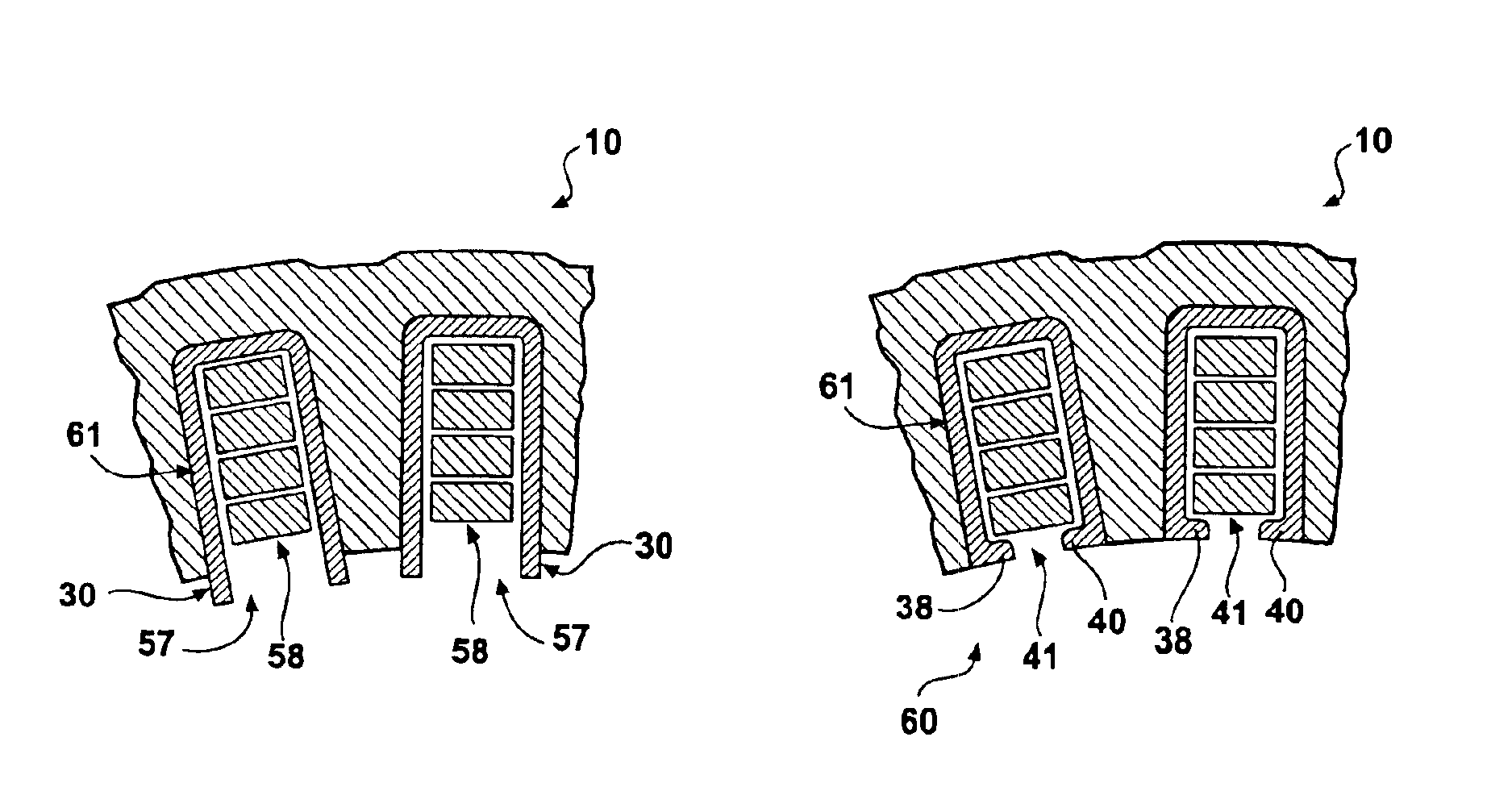
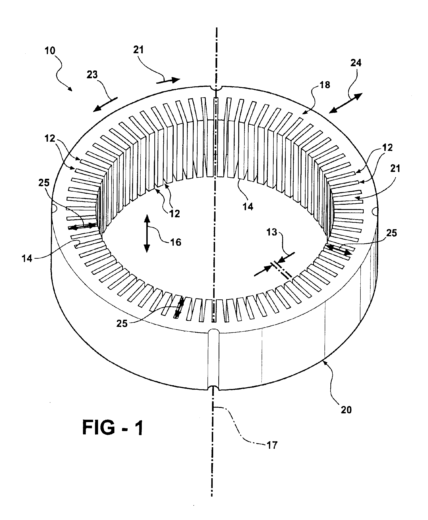
Referring now to FIG. 1, a generally cylindrically-shaped stator core for an dynamoelectric machine (not shown), such as an alternating current generator or alternator, is indicated generally at 10. The stator core 10 is preferably constructed of steel, an iron alloy, or similar magneticallly permeable material and includes a plurality of core slots 12 formed in a circumferential interior surface 14 thereof. The core slots 12 are generally rectangular in cross section and extend in a direction, indicated by an arrow 16, parallel to a central axis 17 of the stator core 10 between a first end 18 and a second end 20 thereof. Alternatively, the core slots 12 could be other shapes other than rectangular, including, but not limited to, a generally square in cross section. The core slots 12 have a generally rectangular volume and define a plurality of teeth 19 therebetween. The teeth 19 are connected to the stator core 10 at a yoke portion 21 thereof. An axially upward direction is defined...


PUM


Abstract

A stator assembly for a dynamoelectric machine in accordance with the present invention includes a stator core having a plurality of core slots in a surface thereof. Each of the core slots define a plurality of tooth members therebetween. A plurality of insert members is each fixedly received by a respective one of the core slots for lining each respective core slot. The insert members have a pair of leg members extending from a base member that form an aperture therebetween. A stator winding includes straight wire segments that are received by the insert members. The straight segments of the stator winding and the insert members are electrically insulated from one another. At least one of the extending leg members is bent over a portion of the straight wire segments in the core slots, narrowing the aperture between the extending leg members.

Description

BACKGROUND OF THE INVENTIONThe present invention relates generally to stators for dynamoelectric machines and, in particular, to an stator assembly for a dynamoelectric machine including a core slot insert member.Dynamoelectric machines, such as alternating current electric generators, or alternators, are well known. Prior art alternators typically include a stator assembly and a rotor assembly disposed in an alternator housing. The stator assembly is mounted to the housing and includes a generally cylindrically-shaped stator core having a plurality of axially-extending core slots formed therein. The core slots define a plurality of teeth therebetween. The teeth are connected to the core by a yoke portion. The rotor assembly includes a motor rotor attached to a generally cylindrical shaft that is rotatably mounted in the housing and is coaxial with the stator assembly. The stator assembly includes a plurality of wires wound thereon, forming windings. The stator windings are formed o...

Claims


Application Information

Patent Timeline
Patent Type & Authority Patents(United States)
IPC IPC(8): H02K3/48H02K1/16H02K3/493H02K1/18H02K3/34
CPCH02K1/165H02K3/48H02K3/493Y02P80/30
Inventor NEET, KIRK E.
Owner VISTEON GLOBAL TECH INC
Why Eureka
Try Eureka