
Adaptive decision slicer

a decision slicer and decision technology, applied in the field of communication systems, can solve problems such as signal degradation, signal decoding difficulty, inaccurate decision, etc., and achieve the effect of accurate decision device operation

Inactive Publication Date: 2005-03-29
MACOM TECH SOLUTIONS HLDG INC
View PDF5 Cites 6 Cited by
  • Summary
  • Abstract
  • Description
  • Claims
  • Application Information

AI Technical Summary

Benefits of technology

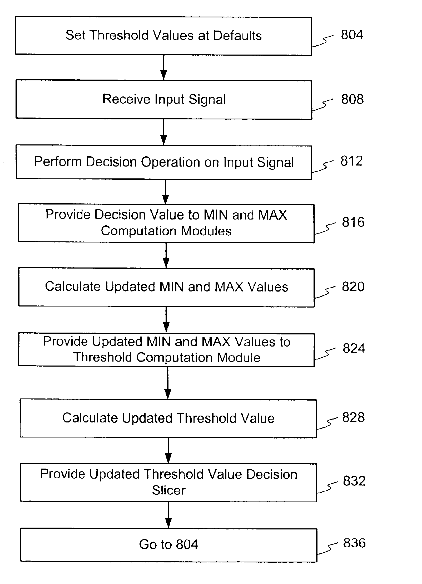
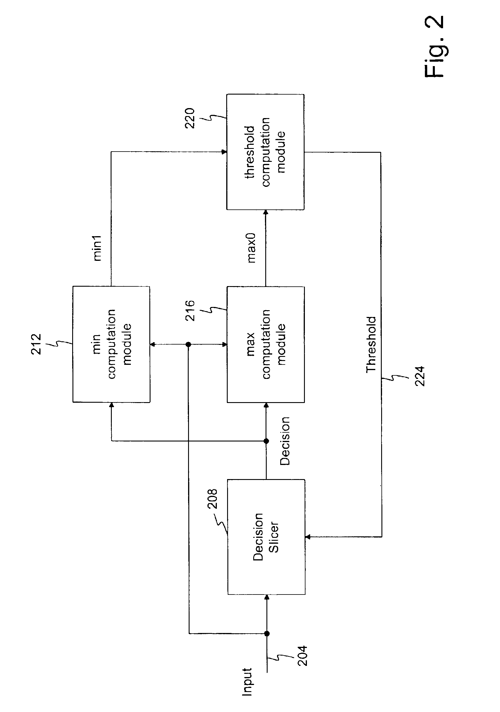
To over come the drawbacks of the prior art the method and apparatus disclosed herein calculates decision thresholds in a decision device based on one or more comparisons between prior received signals, prior threshold values, an average of these signals, or any combination thereof As a result of dynamically calculating the decision thresholds, the thresholds of the decision device adapt to or track changes in the signal that occur over time. Consequently, more accurate decision device operation is enabled.
In one embodiment, the step of scaling the input signal to create a first updated MIN value comprises increasing the value of the signal. It is contemplated that the second control signal may be based on a prior decision value. Furthermore, a MIN value and a MAX value may be associated with each of the two or more decision device output values.

Problems solved by technology

However, at high data transmit rates and when transmitting the signal over long distances, signal degradation may occur, which in turn makes signal decoding difficult.
If the fixed decision boundaries are not set correctly, an inaccurate decision may occur.
In practice, this process presents numerous challenges, which systems of the prior art are not well adapted to overcome.
One challenge arises as a result of the signal passing through a channel.
As the signal passes through a channel, intersymbol interference may occur.
As a result, comparison of the incoming signal, at the sampling times, to the decision boundaries of the decision device may yield incorrect decisions.
Another challenge results from noise introduced into the signal during transmission.
During the decision process, this shift may undesirably result in an inaccurate decision.
It is contemplated that the noise may change over time and is often unknown thereby further compounding the potential error rate.
This proposed solution suffers from at least one drawback in that it only controls the peak of the received signal and as a result, noise variation about zero is never observed or compensated.
The effects of input clock jitter are particularly troublesome since this type of jitter affects a zero value differently than a pulse value.

Method used


Image

  • Adaptive decision slicer
  • Adaptive decision slicer
  • Adaptive decision slicer

Examples


Embodiment Construction

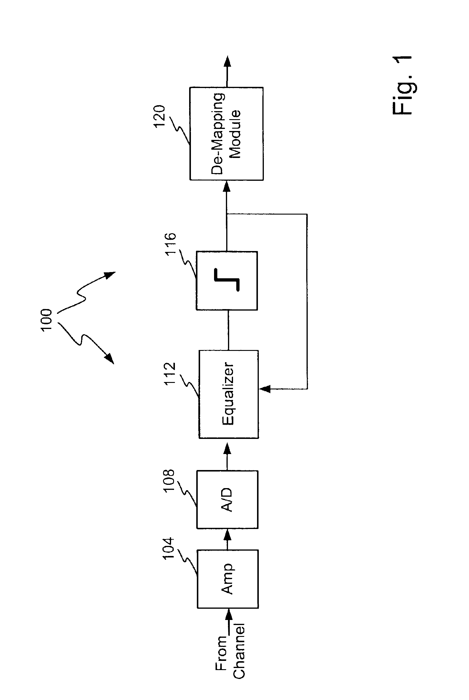
FIG. 1 illustrates an example environment for one embodiment of the invention. This example environment is provided for purposes of discussion and understanding. The invention should not be considered to be limited to this particular environment or field of use. As shown, a receiver 100 comprises an amplifier 104 configured to receive an input from a channel. The amplifier 104 increases the signal magnitude, which may have been attenuated by the channel. The output of the amplifier feeds into an analog to digital converter (A / D) 108, which operates in a manner known in the art. The output of the A / D 108 may connect to an equalizer 112 that is configured to counter the effects of transmission through the channel. The equalizer may comprise any form of feed-forward equalizer, a decision feedback equalizer or any type or number of equalizers or devices configured to compensate for the effects of the channel.

The output of the equalizer 112 connects to a slicer 116. The slicer 116 operat...


PUM


Abstract

A method and apparatus is disclosed for adaptively determining threshold values in a decision device, such as a decision slicer. In one embodiment, a slicer receives one or more updated threshold values during operation to adaptively accommodate changes in the received signal or the channel that may occur over time. The updated threshold value is based on a MIN value and a MAX value. The MIN values represent a value related to a recently received input that was determined to qualify for a particular slicer output and was less than the particular slicer output value. The MAX values represent a value related to a recently received input that was determined to qualify for a particular slicer output and was greater than the particular slicer output value. In one embodiment, the MAX and MIN value computation is based on scaling factors that dampen the rate of change of the threshold value.

Description

FIELD OF THE INVENTIONThe invention relates to communication systems and in particular to a method and apparatus for adaptive decision slicing.RELATED ARTAs is commonly understood, transmission of digital data often occurs over a transmission medium, such as a channel or transmission line, in analog form. Prior to transmission, the digital data may be subject to processing and digital to analog conversion. In some instances, the digital data may be modulated to various voltage levels or have different levels of phase offset introduced. For example, in AMI line coding, there are three signal levels: a positive and negative pulse of predetermined voltage values and a zero volt level. Similarly, pulse amplitude modulation maps the digital data into three or more different voltage levels.Upon receipt, the analog signal, which may assume numerous different voltage levels, is processed and eventually converted back to digital form. As part of the processing, it is often necessary to deter...

Claims


Application Information

Patent Timeline
IPC IPC(8): G11B20/10H04L25/03H04L25/06
CPCG11B20/10203H04L25/062H04L25/03019
Inventor JONES, KEITH R.TREVINO, GILBERTO ISAAC SADAJONES, WILLIAM W.
Owner MACOM TECH SOLUTIONS HLDG INC
Learn More