

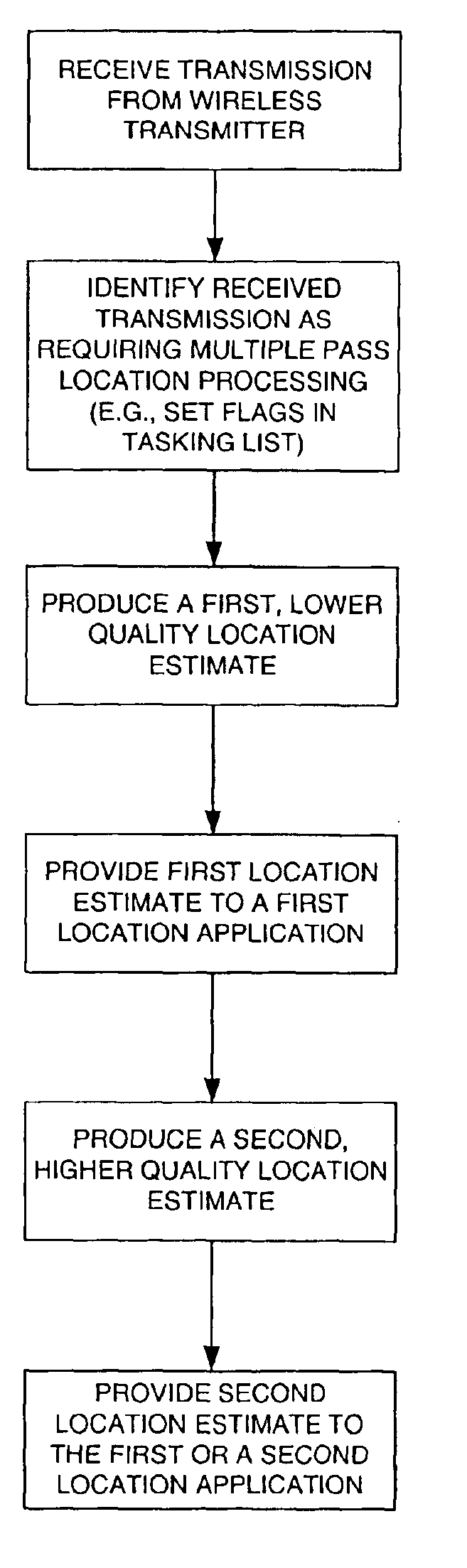
Multiple pass location processor
a wireless transmitter and location processor technology, applied in direction finders using radio waves, emergency connection handling, instruments, etc., can solve the problems of saving enormous costs and affecting the ability of wireless positioning to function properly for most approaches, and achieve the effect of optimizing system accuracy and capacity
- Summary
- Abstract
- Description
- Claims
- Application Information
AI Technical Summary
Benefits of technology
Problems solved by technology
Method used
Image

Examples
Embodiment Construction
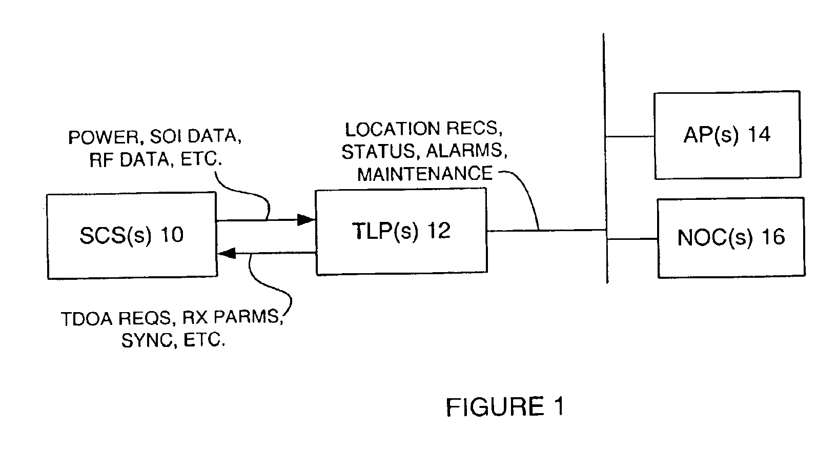
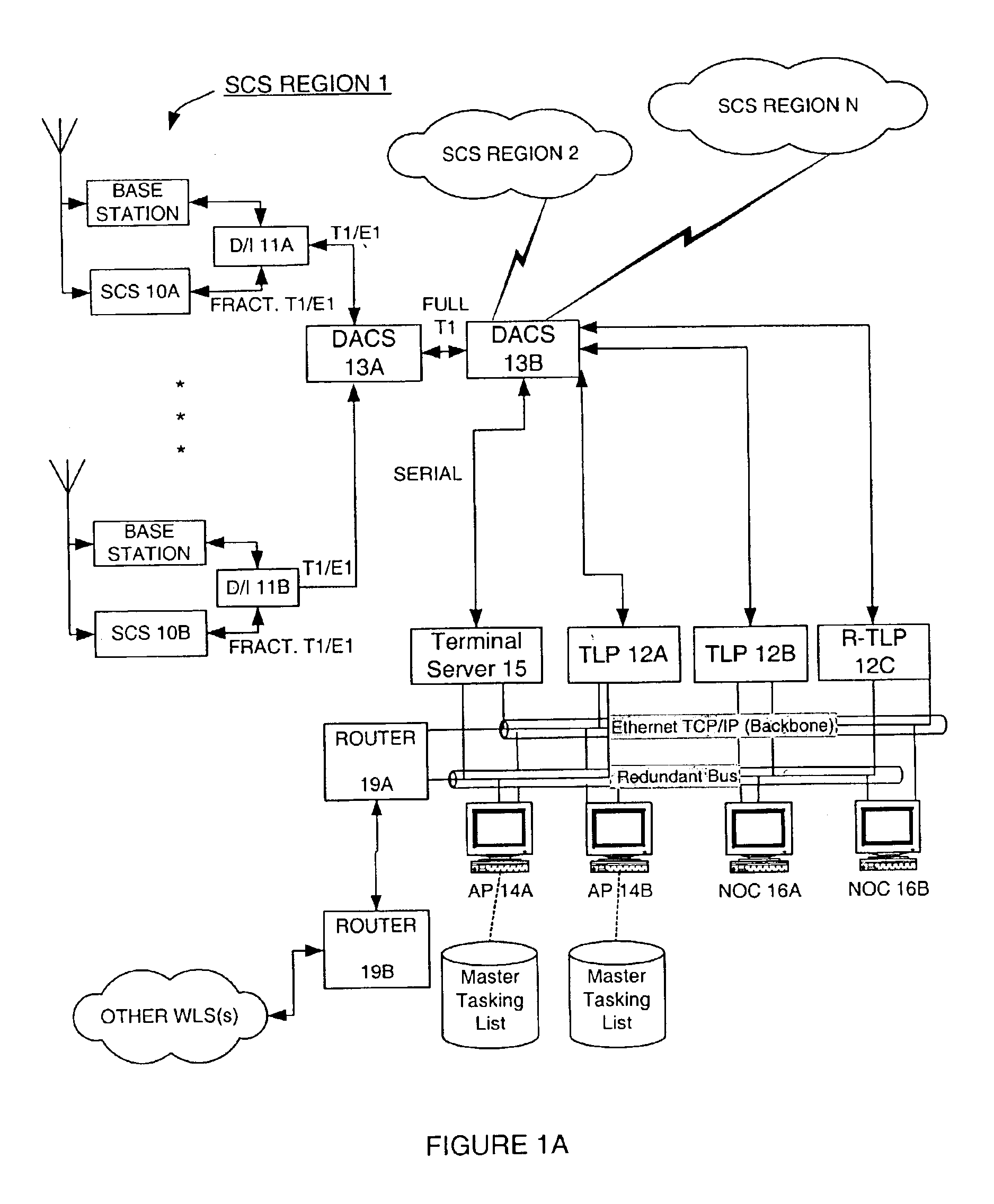
The Wireless Location System (WLS) operates as a passive overlay to a wireless communications system, such as a cellular, PCS, or ESMR system, although the concepts are not limited to just those types of communications systems. Wireless communications systems are generally not suitable for locating wireless devices because the designs of the wireless transmitters and cell sites do not include the necessary functionality to achieve accurate location. Accurate location in this application is defined as accuracy of 100 to 400 feet RMS (root mean square). This is distinguished from the location accuracy that can be achieved by existing cell sites, which is generally limited to the radius of the cell site. In general, cell sites are not designed or programmed to cooperate between and among themselves to determine wireless transmitter location. Additionally, wireless transmitters such as cellular and PCS telephones are designed to be low cost and therefore generally do not have locating c...
PUM
 Abstract
Description
Claims
Application Information