
System of central signature verifications and electronic receipt transmissions

Inactive Publication Date: 2005-03-29
KUO YOU TI +1
View PDF20 Cites 80 Cited by
  • Summary
  • Abstract
  • Description
  • Claims
  • Application Information

AI Technical Summary

Benefits of technology

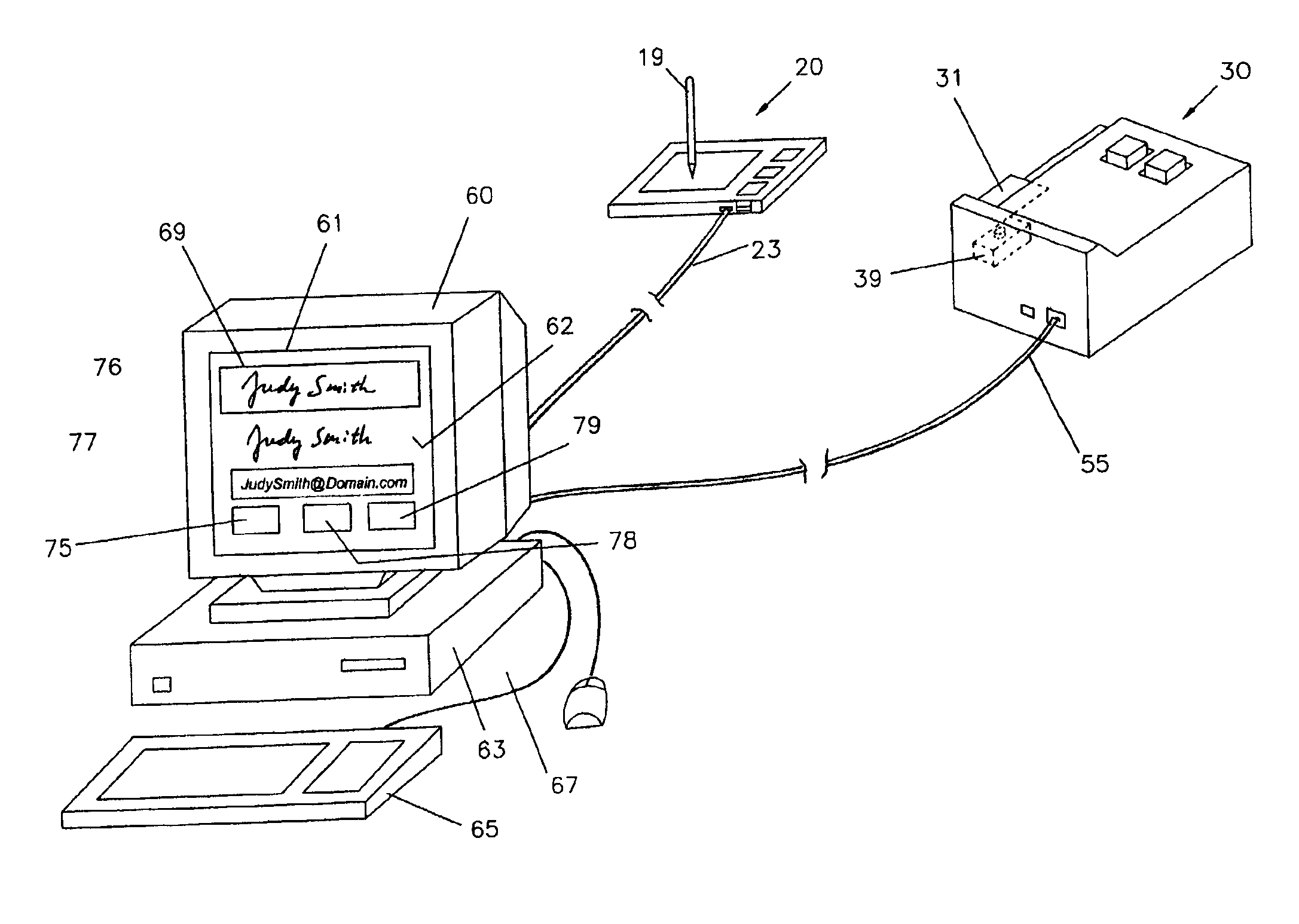
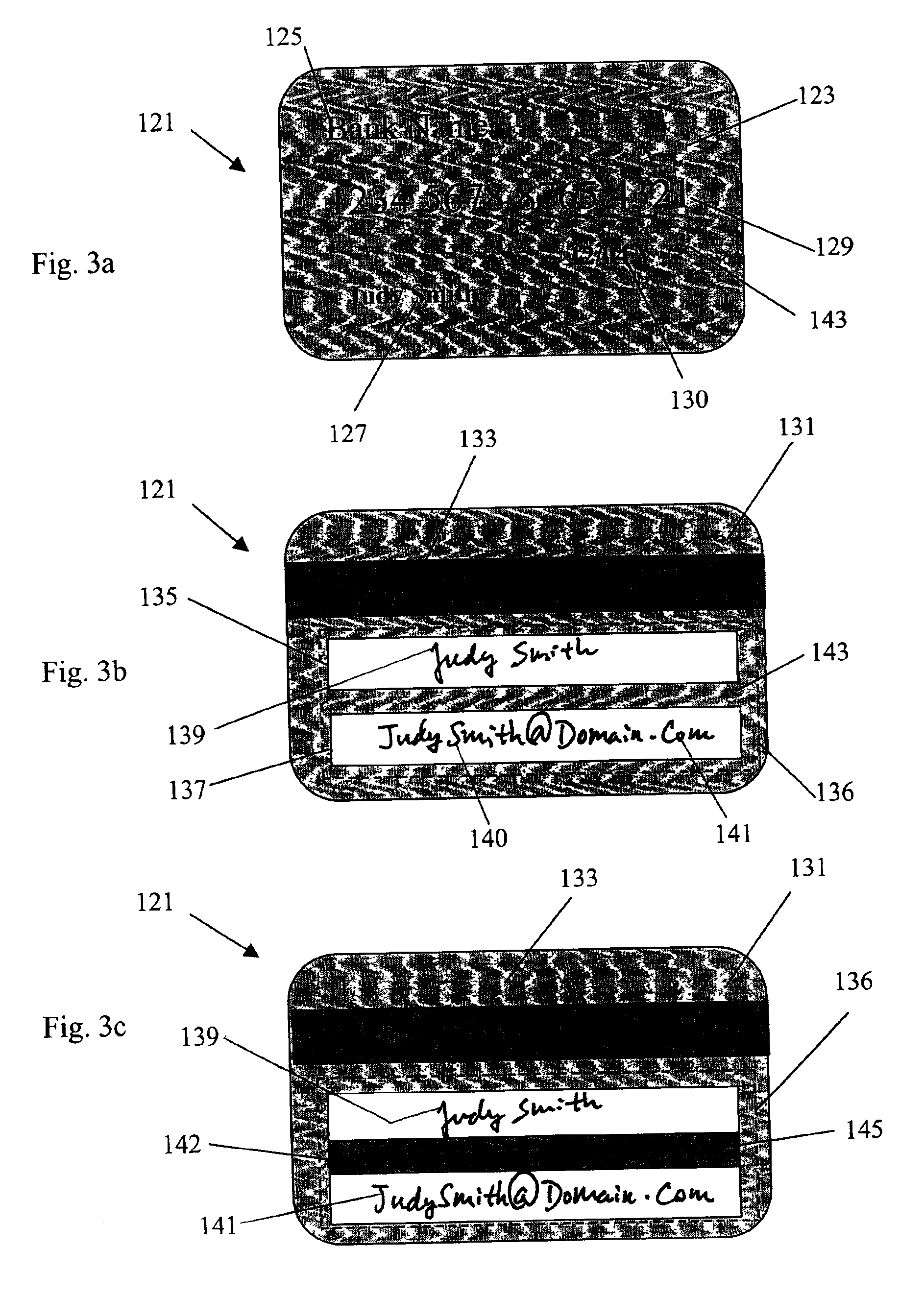
For enabling remote central signature verification, the electronic receipt system of this invention uses a credit card reader having a built-in digital camera for capturing template signature and email address images printed on a credit card. The credit card reader has a glass platen and an optical sensor for registering and detecting a credit card and actuating the digital camera. The characters of the email address are identified by an optical character recognition (OCR) program and the email address is input to the email system for sending an electronic receipt to the card owner. For signature verification, a test signature is entered on a touch-pad input device and transmitted to the display of a host computer. Both the template and the test signatures are normalized with angular adjustment for equalizing their sizes for the convenience of visual inspection. For enforcing the signature verification, three action buttons are provided on the display screen for the store clerk to respond: one for approval of the test signature, one for repeat of the test signature, and another for rejection of the credit card purchase. These computer-assisted features eliminate the need of physical handling the credit card for signature verification and manual input of the email address. By means of having an email address printed on the credit card and using an OCR program, the present invention eliminates the need of pre-registration of an email address for the transmission of electronic receipts.

Problems solved by technology

The methods disclosed heretofore do not adequately satisfy the needs of enforcing signature verification and the privacy of customers' email addresses.
Although the PIN number adds security, the reliability of the intelligent credit card is not ensured as the key pad is not fail-proof and the battery can be out of power.
The intelligent credit card is useless when any such malfunction occurs.
Automatic verification of a signature is extremely difficult because of large variation in a person's signature, even more so when signing at an unusual different pace or physical condition.
Applying to an automated operation, however, the method has a drawback as a current but non-representative signature may be stored and used for the next signature verification.
This lack of a constant reference signature may result in confusion and verification errors.
In view of the free form nature and inconsistency when writing a signature, it is unreliable for an automatic signature verification system to distinguish irrelevant features of a test signature from meaningful characteristics of a template signature.
A major disadvantage of the probability approach is that a set of weighting factors suitable for describing a person's signature variation over time may not be applicable to other persons.
Because it relies on the optical density, the patent does not address possible errors due to the optical density variations of different types of pens and usage conditions when writing signatures.
Also, the patent does not define a characteristic height of a signature for the size normalization.
This time-related method is not applicable to the signature verification of a conventional credit card, as the credit card does not contain any SDC information of the template signature on the card.
Nevertheless, the scanned template signature is obtained by manually swiping the credit card against the stationary scanner by which the swiping motion is not controlled at a constant travel speed.
Consequently, the scanned template signature is subject to image distortion due to the variation of swiping speed in the length of the template signature that may lead to verification errors.
Besides the disadvantage of using two cameras, the method as described does not lead to normalization of thumb print images because of the lack of well defined features in a thumb print for reference for achieving the same orientation and size.
Besides, the inking of a user's thumb is an objectionable invasive action.
Although the display as described displays a signature on the LCD screen, it does not enable concurrent display of the as-written (test) signature with the (template) signature contained in the credit card for verification.
This pre-registration requirement is objectionable to users who prefer privacy and nondisclosure of their email address for commercial use.
The use of a dedicated pen is a severe limitation for this method and the feature of disappearing signature has no advantages compared to a paper receipt having a visible signed signature.
Furthermore, it is not desirable to manually enter the email address by the operator or the credit card user at the POP terminal as it is a time consuming practice.
Additionally, a smart card containing broad-based information is undesirable, as disclosure of one type of information (in credit card use) does not prevent disclosure of other information (such as other bank account data) when the smart card is being processed in a computerized device.
However, none of the prior art patents are adequately applicable to the need of identifying the email address printed on a credit card.
However, the process of less than 100% confidence level can lead to errors in identifying the email address.
Without the exact correct email address, the email system of the computer network cannot deliver the email to the customer.
Despite the prior art on signature verification and electronic receipts, there has been no system that addresses the need of enforcing signature verification and the selectivity of receiving an electronic receipt.

Method used


Image

  • System of central signature verifications and electronic receipt transmissions
  • System of central signature verifications and electronic receipt transmissions
  • System of central signature verifications and electronic receipt transmissions

Examples


Embodiment Construction

Conventionally, a credit card is used for purchase transactions at a cash register or at a point-of-purchase terminal. A test signature is signed directly on a paper receipt or entered on a touch-pad input device and transmitted to a terminal printer to print on a paper receipt. A cashier is required handling the credit card for inspecting the test signature signed on the receipt in comparison with the template signature signed on the credit card. In the electronic receipt system of present invention, the signature verification is performed without manually handling the credit card by a cashier as described below.

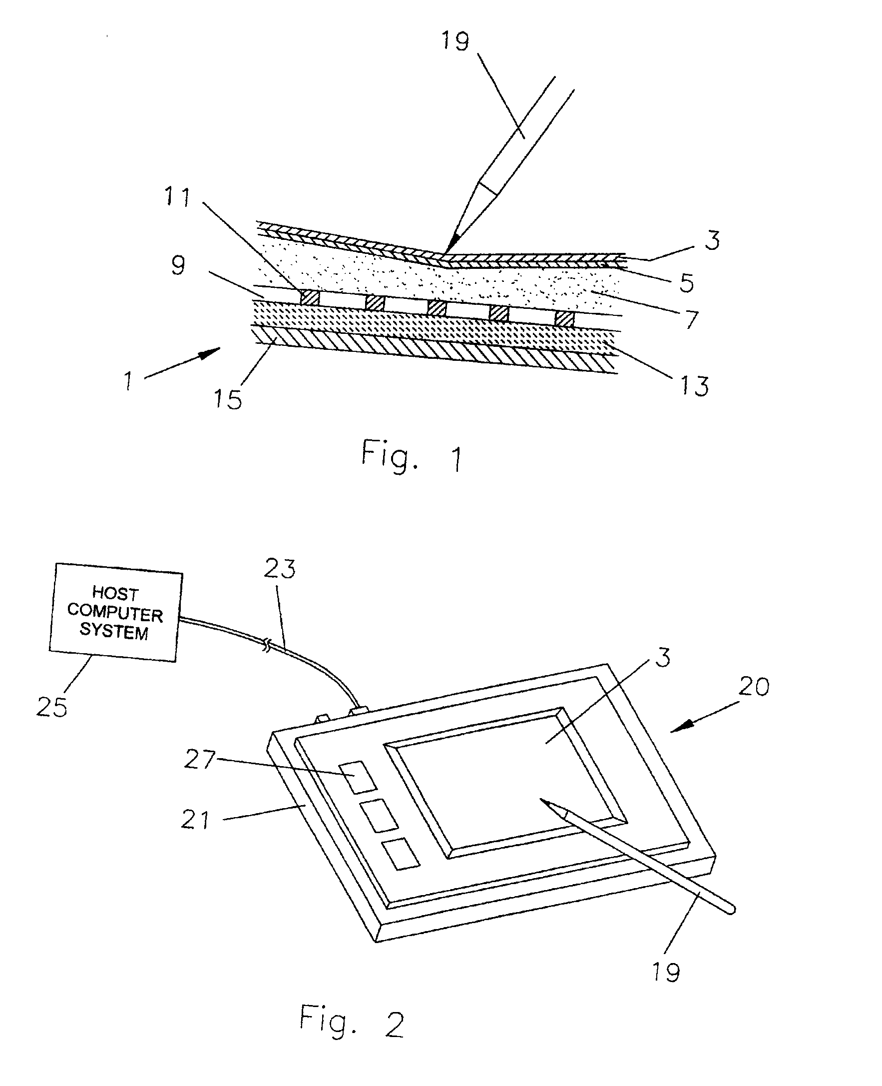
FIG. 1 shows touch pad 1 which is preferably capacitive-type. A capacitive-type touch pad comprises an insulating layer 13 having an orthogonal matrix of first parallel conductive traces 11 aligned in the X-direction disposed on a first surface, and second parallel conductive traces 15 aligned in the Y-direction disposed on an opposed second surface. The conductive traces 1...


PUM


Abstract

A credit-card reader having a built-in digital camera for capturing a template signature and an email address on a credit card. The email address is identified by an optical character recognition program and input to an email system. A test signature is entered on a touch-pad input device and both the test and the template signatures are normalized and displayed for verification. Action buttons are provided on the display screen for enforcing the signature verification actions. The system enables the transmission of an electronic receipt selectively controlled by the customer and eliminates the needs of physically handling a credit card for signature verification and manual input or pre-registration of an email address for an electronic receipt. The computer-assisted features enables a central system of signature verification for purchase transactions at self-service check-out counters.

Description

BACKGROUND OF THE INVENTIONCredit cards are widely used for purchasing products and services. Conventionally, a credit card is swiped through a magnetic stripe reader connected to a point-of-purchase terminal. The magnetic stripe reader reads the customer's account information embedded in a magnetic stripe on the credit card and transmits the data of purchase transaction electronically to the credit card issuer's communication network for purchase authorization. The approval or rejection of the credit card purchase is electronically transmitted back to the point-of-purchase terminal. At the point-of-purchase terminal, a store clerk has the customer sign a paper receipt. The store clerk is required to verify the signature on the paper with respect to the signature on the backside of the credit card. However, signature verification is seldom performed for being intrusive and time consuming and it is neglected in the case of using self-service credit card readers, by which credit cards...

Claims


Application Information

Patent Timeline
IPC IPC(8): G06K9/00G07C9/00
CPCG07C9/00047G06K9/00154G07C9/24G06V40/30
Inventor KUO, YOU-TIKUO, SHIRPHONE
Owner KUO YOU TI
Learn More