
Confocal-reflection streak lidar apparatus with strip-shaped photocathode, for applications at a wide range of scales

a lidar and strip-shaped technology, applied in the field of turbid medium volume imaging, can solve the problems of insufficiently optimizing bench-scale lidar configurations, most or all previous lidar workers have not fully appreciated the critical importance of confocal conditions, and the speed of electronic and mechanical scanners is eliminated. , to achieve the effect of enhancing the target signature, reducing the cost of optical energy, and reducing the cost of operation

Inactive Publication Date: 2005-03-29
ARETA ASSOC
View PDF13 Cites 39 Cited by
  • Summary
  • Abstract
  • Description
  • Claims
  • Application Information

AI Technical Summary

Benefits of technology

In accordance with a primary advantage of the present invention, the need for fast digitizing electronics and mechanical scanners is eliminated. (As will be seen, however, in certain of the applications outlined above, at least in principle fast electronics can be substituted for a streak tube.)

Problems solved by technology

Probably the reason for this is that prior artisans have not fully appreciated how to use lidar to obtain a direct distance-to-depth mapping in a simple natural real-time display, capable of direct volume implications.
Furthermore, most or all previous workers in lidar have failed to appreciate the critical importance of the confocal condition—though that condition is recognized in other fields.
Accordingly bench-scale lidar configurations have not been reasonably optimized.
At ocean-volume scale, lidar systems heretofore have not been made effective at all.
In this case, in addition to the failures of recognition outlined in the preceding paragraph, previous workers have evidently overlooked the potential use of streak lidar.
That configuration is not Takaoka's invention, and he teaches nothing about its effective use.
Such methods require the use of mechanical scanners that are slow and difficult to build, particularly if they are to be mounted on aircraft.
Several drawbacks are associated with the range-gating technique.
Range gating does not allow utilization of all, or substantially all, of the information returned from each pulse to create three-dimensional data sets.
This operating arrangement constitutes a monumental waste of optical energy.
Additionally, a full-depth data set cannot be created from a single pulse.
Despite the availability of such techniques, existing lidar systems are limited by the size of the receiver optics that can be used in a scanner.
Generally the light reflected from targets that are deeply positioned, or suspended in a very turbid medium, is weak.
Although large-diameter optics can aid in maximizing the amount of light collected from weak returns, the size of the optics that can be used in a scanner is restricted by the size of the moving prisms or mirrors.
The scanning problem, however, is still formidable and restricts the size of the apertures that can be used.
Moreover, volume scanning systems are very expensive, and require considerable power and weight.
Consequently, for large-scale applications the ability to install such systems in aircraft or other vehicles is restricted.
Furthermore, those systems that utilize range gating, instead of volume scanning, suffer from poor range resolution and area coverage.
When a target object is at a different depth from the expected, the optical return is subtracted as well as the background, and poor performance results.
The transillumination technique, however, yields only two-dimensional images and cannot determine the depth of a tumor.
Such data are subject to relatively poor detection range.

Method used


Image

  • Confocal-reflection streak lidar apparatus with strip-shaped photocathode, for applications at a wide range of scales
  • Confocal-reflection streak lidar apparatus with strip-shaped photocathode, for applications at a wide range of scales
  • Confocal-reflection streak lidar apparatus with strip-shaped photocathode, for applications at a wide range of scales

Examples


Embodiment Construction

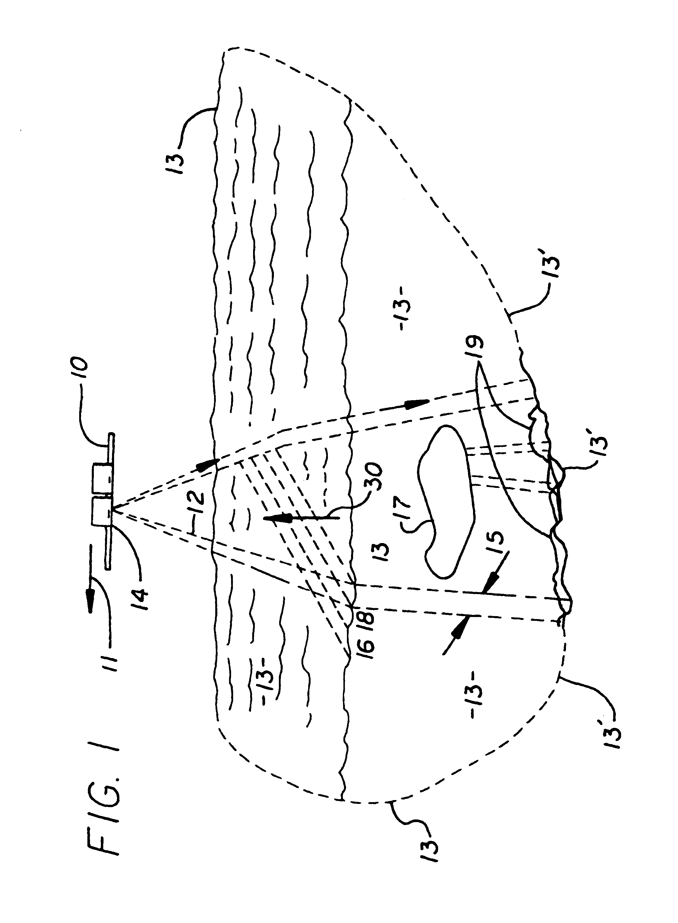
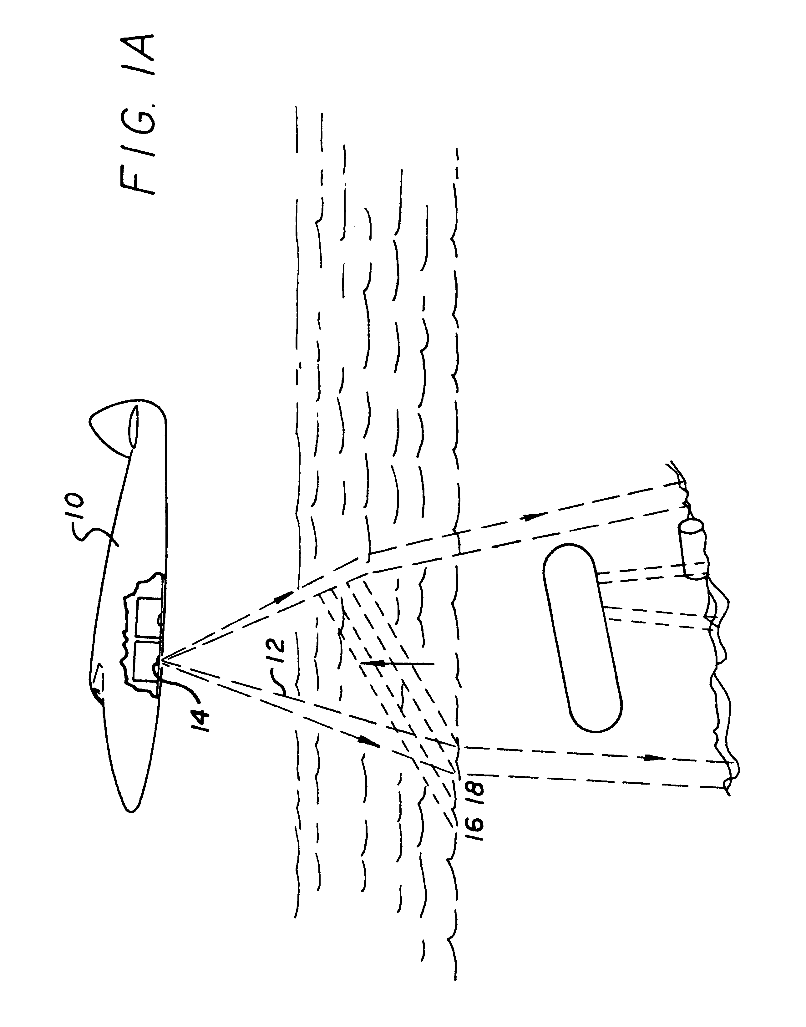
The present invention provides a system for detecting targets located in a light-reflecting medium, such as dirty, hazy or foggy air; and such as water or living tissue. The system can be used to observe a water interface, the structure of the medium—including the distribution of particulate matter and suspended or otherwise embedded bodies—and a bottom or far-interior-surface profile. More particularly the invention can be used to detect objects in any medium through which light can pass, even if absorbed and scattered, provided that some substantially directly reflected light can be obtained.

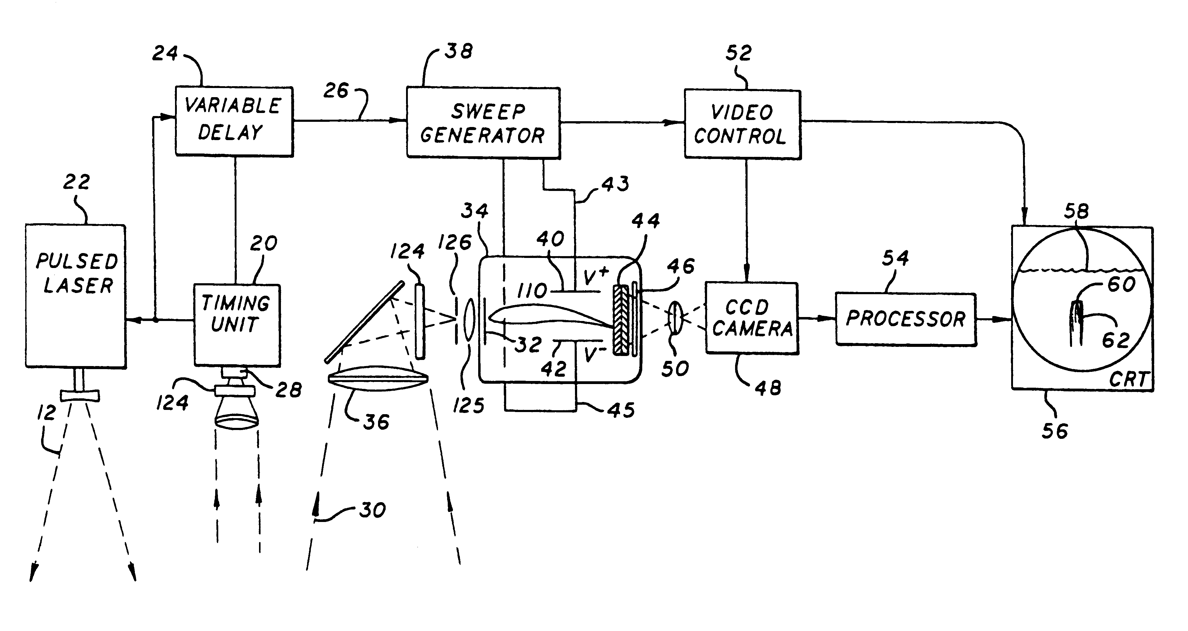
The system includes a light source for producing a series of discrete narrow, fan-shaped pulse beams which have a modified non-uniform intensity distribution to produce uniform signal-return. The reflected portions of the pulse beam are received by a detection system comprising receiving optics, a streak tube and an imaging area detector.

In operation, the invention by some means physically shi...


PUM


Abstract

The system images the volume of a turbid medium and detects the contents. The medium can be water or air, or living tissue, or almost any other material which is at least partially light-transmissive. The system includes a light source for producing a series of discrete fan-shaped pulse beams that are substantially uniform in intensity or have been peaked at the edges of the fan to illuminate sections of the medium, a streak tube with a large, thin-slit-shaped photocathode for collecting the maximum amount of light from weak returns, a field-limiting slit disposed in front of the cathode for removing multiply scattered light, a large-aperture optical element for collecting and focusing the reflected portions of the pulse beam on the field-limiting slit and the cathode, and an array of detectors. A volume display of the medium is generated by translating the transmitter and receiver normal to the longitudinal axis of the pulse beam, to illuminate adjacent sections of the medium, and combining the sections to provide a volume display. All, or substantially all, of the light returned from each pulse beam is used. Vehicle motion can be used to provide the scan of the beam. Applications range from foggy sky surveillance at multiple-kilometer scale to location of fractional-millimeter tumors in a human breast.

Description

BACKGROUND1. Field of the InventionThis invention relates generally to imaging the volume of a turbid medium, together with objects embedded or suspended in such a medium; and more particularly to use of streak-lidar apparatus to monitor phenomena at an extremely broad range of scales—including detection of a tumor less than a millimeter across, in living tissue; or an underwater object in the ocean, or vehicles in fog, or a variety of other objects in turbid media.2. Prior ArtThe present invention has applications spanning a range of sizes, and is believed to integrate diverse, heretofore nonanalogous fields. For reasons to be explained in this document, these fields have not previously been linked.These application fields include imaging of volumes of the atmosphere with aircraft moving through such volumes—over a range (and atmospheric volume) on the scale of kilometers. It also includes imaging of ocean volumes—together with submarines, sunken ships, submerged fuel drums and the...

Claims


Application Information

Patent Timeline
IPC IPC(8): G06K9/00G01S17/89G01S7/483G01S17/42G01S17/95
CPCG01S7/483G01S17/95G01S17/89G01S17/42Y02A90/10
Inventor BOWKER, J. KENTLUBARD, STEPHEN C.MCLEAN, JOHN W.
Owner ARETA ASSOC
Learn More