Combined wavefront coding and amplitude contrast imaging systems

a technology of contrast imaging and wavefront coding, applied in the field of contrast imaging, can solve the problems of not being illuminated sufficiently, not directly available final image using wavefront coding, etc., and achieve the effects of improving contrast imaging of phase objects, increasing depth of field and controlling focus-related aberrations

Inactive Publication Date: 2005-03-29
UNIV OF COLORADO THE REGENTS OF +1
View PDF102 Cites 105 Cited by
  • Summary
  • Abstract
  • Description
  • Claims
  • Application Information

AI Technical Summary

Benefits of technology

An object of the present invention is to improve Contrast Imaging of phase objects by increasing depth of field and controlling focus-related aberrations. This is

Problems solved by technology

Unlike the traditional imaging system, the final image using Wavefront Coding is not directly available at the image plane.
Without Wavefront

Method used


Image

  • Combined wavefront coding and amplitude contrast imaging systems
  • Combined wavefront coding and amplitude contrast imaging systems
  • Combined wavefront coding and amplitude contrast imaging systems

Examples


Embodiment Construction

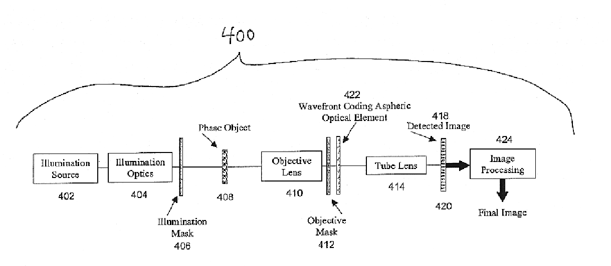
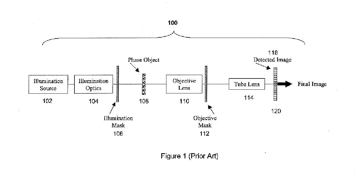
Wavefront Coding can be combined with traditional objectives and objective masks in Amplitude Contrast systems, as shown in FIG. 4, to achieve an increased depth of field in an optical and digital imaging system. This can be explained through inspection of the ambiguity functions and modulation transfer functions (MTFs) of the related traditional, amplitude contrast systems, and Wavefront Coded imaging systems, as shown in FIGS. 5-9. FIG. 10 shows a real world image taken with a system having only Amplitude Contrast, compared to a system combining Amplitude Contrast and Wavefront Coding and post processing.

FIG. 4 shows a combined Extended Depth of Field (EDF) and Amplitude Contrast Imaging system 400 including Wavefront Coding and post processing in accordance with the present invention. The general Amplitude Contrast imaging system of FIG. 1 is modified with a special purpose generalized aspheric optical element 422 and image processing 424 of the detected image to form the final i...


PUM


Abstract

The present invention provides extended depth of field or focus to conventional Amplitude Contrast imaging systems. This is accomplished by including a Wavefront Coding mask in the system to apply phase variations to the wavefront transmitted by the Phase Object being imaged. The phase variations induced by the Wavefront Coding mask code the wavefront and cause the optical transfer function to remain essentially constant within some range away from the in-focus position. This provides a coded image at the detector. Post processing decodes this coded image, resulting in an in-focus image over an increased depth of field.

Description

BACKGROUND OF THE INVENTION1. Field of the InventionThis invention relates to apparatus and methods for improving contrast imaging of objects which are transparent or reflective, and also vary in thickness or index of refraction, using wavefront coding.2. Description of the Prior ArtMost imaging systems generate image contrast through variations in reflectance or absorption of the object being viewed. Objects that are transparent or reflective but have variations in thickness can be very difficult to image because the majority of the image contrast typically is derived from variations in the reflectance or absorption of the object. These types of objects can be considered “Phase Objects”. Various techniques have been developed over the years to produce high-contrast images from phase objects. These techniques allow high contrast images from essentially transparent objects that have only variations in thickness or index of refraction. These techniques generally modify both the illumi...

Claims


Application Information

Patent Timeline
IPC IPC(8): G02B27/50G02B27/00
CPCG02B27/50G02B27/0025
Inventor DOWSKI, JR., EDWARD RAYMOND
Owner UNIV OF COLORADO THE REGENTS OF
Why Eureka
Try Eureka