Design of storage devices and processes for their fabrication have become quite sophisticated and have resulted in very low process cost for fabrication and very small
memory cell area.
Nevertheless, memory sells, particularly of the dynamic type which store data capacitively, are relatively delicate devices and may be subject to damage or deterioration during manufacture or after being placed in service.
Nevertheless, system failures may be attributed to damage caused by external elements, minor manufacturing imperfections and / or aging of the materials, Damage from external elements could
impact the correct functioning of an electronic system or any part thereof at any time during its useable life.
However, minor manufacturing imperfections are the main cause of system failures at early stages of system operation while aging is the dominant cause of system failures at, later stages of the time of the system.
These factors may make embedded memories somewhat more prone to failures due to minor manufacturing imperfections and aging and thus must be tested periodically after being placed in service in addition to manufacturing level and board level testing.
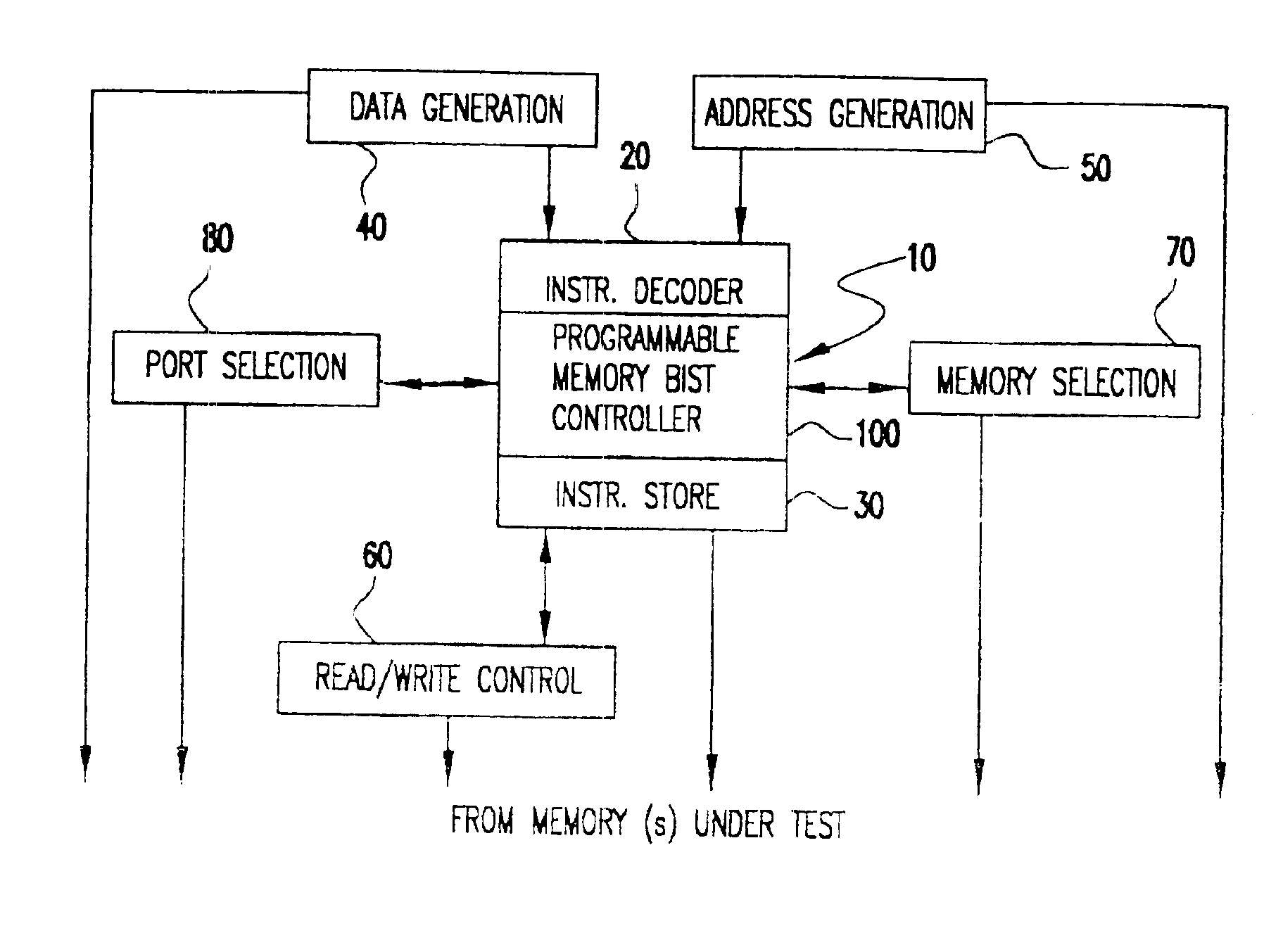
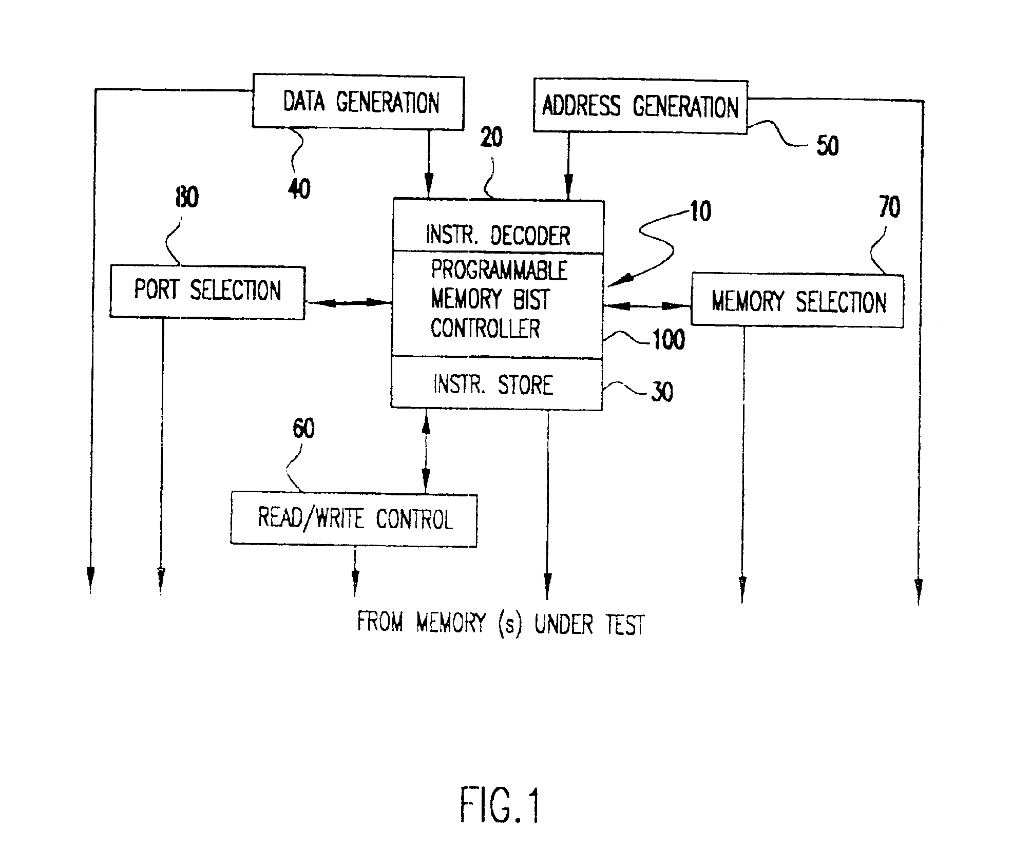
However, in such a case, the hardware dedicated to manufacturing level and board level testing which is generally provided as a built-in self-test arrangement would have no function after the system is placed in service while the additional hardware provided for
system level testing would increase the hardware overhead for testing of all types.
However, access to embedded memories for testing is often difficult, particularly where chip space and external connections are at a premium.
The amount of chip space which can be efficiently allocated to a BIST arrangement is very limited, generally to about 2% of the area of the storage devices to be tested.
At the present state of the art, maintaining the BIST arrangement within such a chip area constraint presents a major challenge, particularly where the memory structure is complex and extended numbers of sequences of signals are required to adequately test the memory and / or to capture signals from the memory for evaluation in the course of the self-test.
Even when the chip area is limited to a small percentage of the area of the memory to be tested, the chip space is considered to be inefficiently used since the BIST arrangement is not used in the other intended functions of the chip.
Nevertheless, the use of a BIST arrangement may be the only practical technique for accessing the
signal lines necessary for testing of an
embedded memory.
In the former case (e.g. where storage is non-volatile) no loading of the test instructions is necessary and may not be possible.
Also, ROM and small RAM modules complicate the overall testing of the system.
However, the BIST modules that use register files as their instruction store module cannot be used for
system level tests.
Therefore, the BIST arrangement is confined to use in lower level tests where an external control of such initialization and source of
test algorithm is available and thus represents a substantial inefficiency in utilization of chip space, as alluded to above, even though the BIST arrangement is substantially essential to assure functionality of a chip and the board which includes it.

