Illumination device

a technology of illumination device and front light, which is applied in the direction of lighting and heating equipment, instruments, signs, etc., can solve the problems of low directivity of the bulb used in the former method, decrease the confirmation lower the design property of the portion of the license plate, so as to achieve efficient heightening of the license plate

Inactive Publication Date: 2005-04-05
TOYODA GOSEI CO LTD
View PDF12 Cites 39 Cited by
  • Summary
  • Abstract
  • Description
  • Claims
  • Application Information

AI Technical Summary

Benefits of technology

In view of the above mentioned problems, the invention has been built, and it is accordingly an object of the invention to offer an illumination device for license plate of an simple structure enabling to compose the license plate to be thin type (compact), another object of the invention to offer an illumination device for general purpose application, and a further object of the invention to offer an illumination device enabling to efficiently heighten visibility of the license plate.
Depending on the processing treatment at the terminal face of the light pipe, there is a probable case that a leaking light can be almost ignored. Further, depending on viewing, the light observation from the terminal face (and / or the end part) of the light pipe has an ornamental effect. In addition, the terminal face (and / or the end part) of the light pipe is subjected to a cutting treatment, so that the luminous embodiment may be turned out to produce more ornamental effects. In other words, the light is positively made luminous from the terminal face (and / or the end part) of the light pipe for making use of this effect to additive ornament.

Problems solved by technology

Since the light of the bulb employed in the former method is low in directivity, even if the bulb is installed, for example, in opposition to the license plate, some parts of the light emitted from the bulb go to other directions than the license plate.
Such lights are not used to illumination of the license plate, besides cause to decrease confirmation of the license plate, and further lower a design property in the portion of the license plate.
From the designing viewpoint, it is not desirable that the bulb itself is observed from the outside.
As a result, the part of the license plate is inevitably thick along a full length of the car.
On the other hand, also in the license plate of the letter lighting system, it is necessary to secure a space for disposing back lights at the inside of the license plate, and as a whole, an apparatus becomes thick.
In addition, owing to necessity of using a specially processed license plate, ordinarily used license plates cannot be utilized and are lack in general purposes.
Further, a structure is complicated and high in production cost.

Method used


Image

  • Illumination device
  • Illumination device
  • Illumination device

Examples


first embodiment

(First Embodiment)

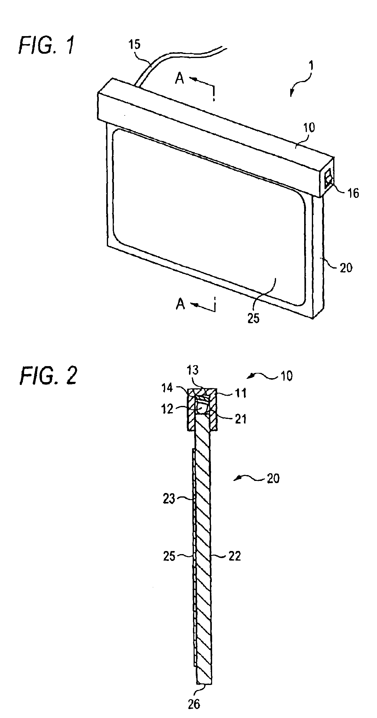
The structure of the invention will be explained in more detail by use of the embodiments. FIG. 1 is a perspective view showing the planar lighting unit 1 as one of the embodiments. FIG. 2 is a cross sectional view along A—A line of FIG. 1.

The illumination device is substantially composed of the light source unit 10 and the light pipe 20. The light pipe 20 is shaped in plane of about 4 mm thickness, and a material quality is an acrylic resin. The light diffusing layer 25 as light diffusing means is formed almost allover the observing face (a design face) 23 of the light pipe 20. The light diffusing layer 25 is a layer where acrylic beads having average diameter of about 6 μm are dispersed in the base material of the acrylic resin, and has thickness of about 12 μm. The amount of containing the acrylic beads in the light diffusing layer 23 is, by weight standard, 1 to 100 of the base material. Such a light diffusing layer 25 is formed by printing or coating a clear i...

second embodiment

(Second Embodiment)

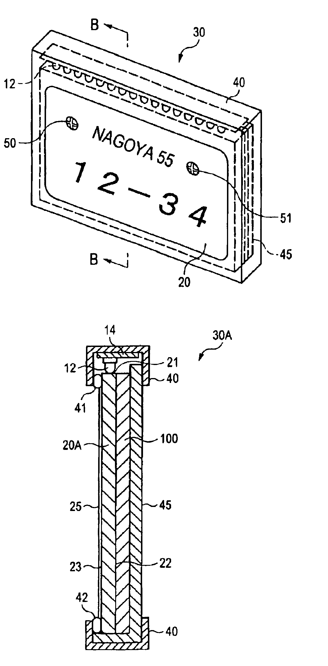
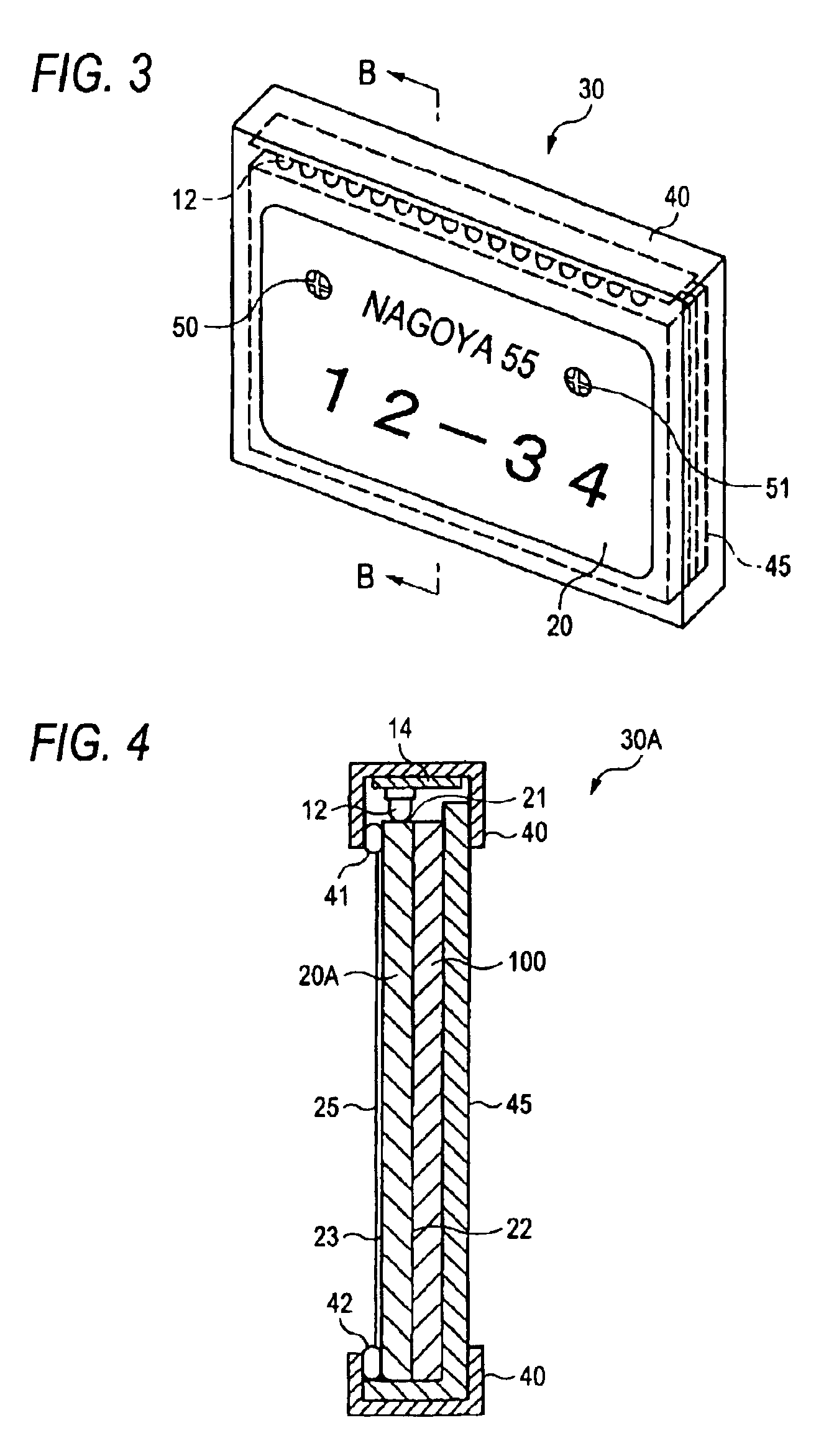
Next, explanation will be made to the illumination device 30A of the license plate as the second embodiment of the invention. FIG. 3 is a perspective view showing the illumination device 30A. FIG. 4 is a cross sectional view along B—B line of FIG. 3. FIG. 5 is a cross sectional view showing attachment of the illumination device 30A. In each of the drawings, the same members as those of the planar lighting unit 1 will be given the same numerals for omitting explanations therefor.

The illumination device 30A is almost composed of the light pipe 20A, the plural LEDs 12 mounted on the base plate 14, the support plate 45 and the casing 40. In this embodiment, as the LEDs 12, the white luminous LEDs of cannonball and the white color are used in 16 pieces in total. The LEDs 12 are supplied with electric power via a wiring (not shown).

The support plate 45 is a member provided for securing the position of the license plate 100. As showing in FIG. 4, the license plate 100 is...

third embodiment

(Third Embodiment)

FIG. 6 is a cross sectional view showing an illumination device 30B according to the third embodiment of the invention.

In the third embodiment, the light pipe 20B comprises a plane-like material of the acrylic resin group of about 4 mm thickness, and is almost the same in the plane-viewed shape as the license plate 100. Incidentally, the license plate 100 is not exclusively used to the illumination device 30B, but broadly used in general.

In this embodiment, although light diffusing layer is not provided, substantially triangular grooves continuing in dot in a vertical direction are innumerably formed alternatively so as to constitute light diffusing means in a horizontal direction on the surface 112 of the light pipe at the opposite side to the license plate 100. The innumerable grooves are formed more closely as becoming farther from the upper end face 113. Specifically, at the range nearest to the side of the upper end face 113, the grooves of about 1.77 mm lengt...


PUM


Abstract

The illumination device comprises at least one light source, and a light pipe positioned at the front side of a license plate, and a light diffusing means. A light of the light sources is led, the light pipe emitting a leading light from the surface of the license plate face. The light emitted from the observed face is diffused by the light diffusing means. The light diffusing means is provided with, rugged portions of an observed face opposite to a light emitting face, or, a light diffusing layer composed of two or more kinds of light transmitting materials, refractive indexes of which are different each other, on the observing face, and a light led from a light leading face is reflected and diffused on the light diffusing layer.

Description

The present application is based on Japanese Patent Applications Nos. 2001-380519 and 2002-166442, the entire contents of which are incorporated herein by reference.BACKGROUND OF THE INVENTION1. Field of the InventionThe present invention relates to a front light type lighting device adapted to a license plate part of a vehicle, or lightening of many kinds of liquid crystal displays etc. and particularly to an illumination device for the license plate.2. Related ArtAs methods for heightening visibility of a car license plate, there are a method which irradiates light of bulbs positioned above or below the license plate to the surface of the license plate, and a method of using the license plate of a letter lighting system. As to the license plate of the letter lighting system, many improvements are proposed in Japanese Patent Publication Nos. JP H10-129344A, JP 2000-313279A and JP H10-119669A.Since the light of the bulb employed in the former method is low in directivity, even if th...

Claims


Application Information

Patent Timeline
Patent Type & Authority Patents(United States)
IPC IPC(8): B60Q1/56B60Q1/26F21V8/00G02B6/00
CPCB60Q1/56G02B6/0081G02B6/0055G02B6/005
Inventor MATSUURA, YOSHIHIROIWASA, TADANOBUMISAWA, AKIHIROTATEWAKI, YASUMASA
Owner TOYODA GOSEI CO LTD
Why Eureka
Try Eureka