Magnetic thin film interference device or pigment and method of making it, printing ink or coating composition, security document and use of such a magnetic thin film interference device

Inactive Publication Date: 2005-04-05
SICPA HLDG SA
View PDF8 Cites 56 Cited by
  • Summary
  • Abstract
  • Description
  • Claims
  • Application Information

AI Technical Summary

Benefits of technology

The magnetic layer 4 is covered by a reflector layer 3, 3′ made of a good light reflecting material, such as aluminum, aluminum alloy, chromium, silver, gold, etc. This allows the magnetic OVP to be optimized simultaneously for good optical performance as well as for customer-designed magnetic properties. In this way, different varieties

Problems solved by technology

Both reflected parts of the incident light finally recombine and interfere with each other.
Constructive or destructive

Method used


Image

  • Magnetic thin film interference device or pigment and method of making it, printing ink or coating composition, security document and use of such a magnetic thin film interference device
  • Magnetic thin film interference device or pigment and method of making it, printing ink or coating composition, security document and use of such a magnetic thin film interference device
  • Magnetic thin film interference device or pigment and method of making it, printing ink or coating composition, security document and use of such a magnetic thin film interference device

Examples


Embodiment Construction

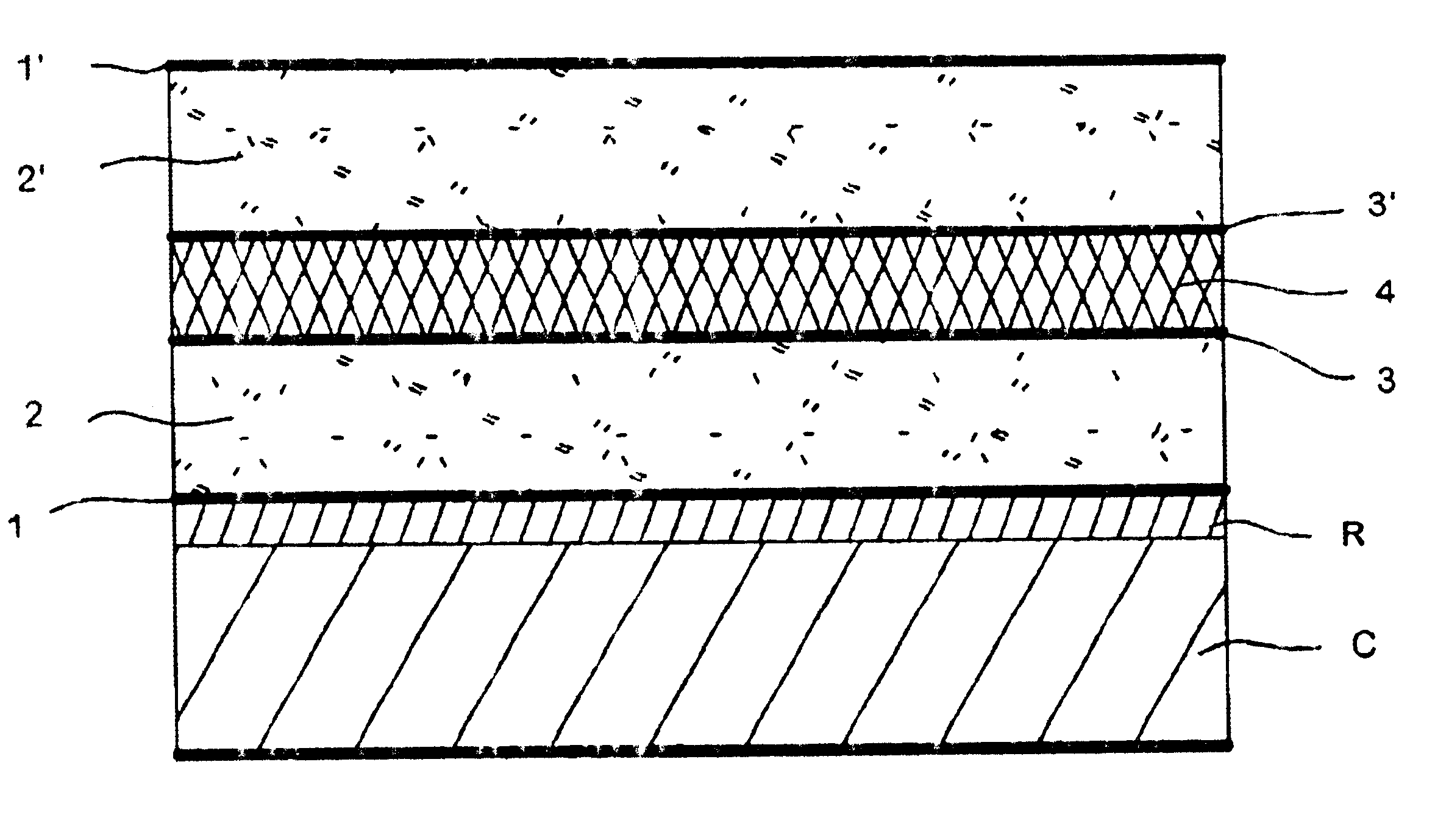
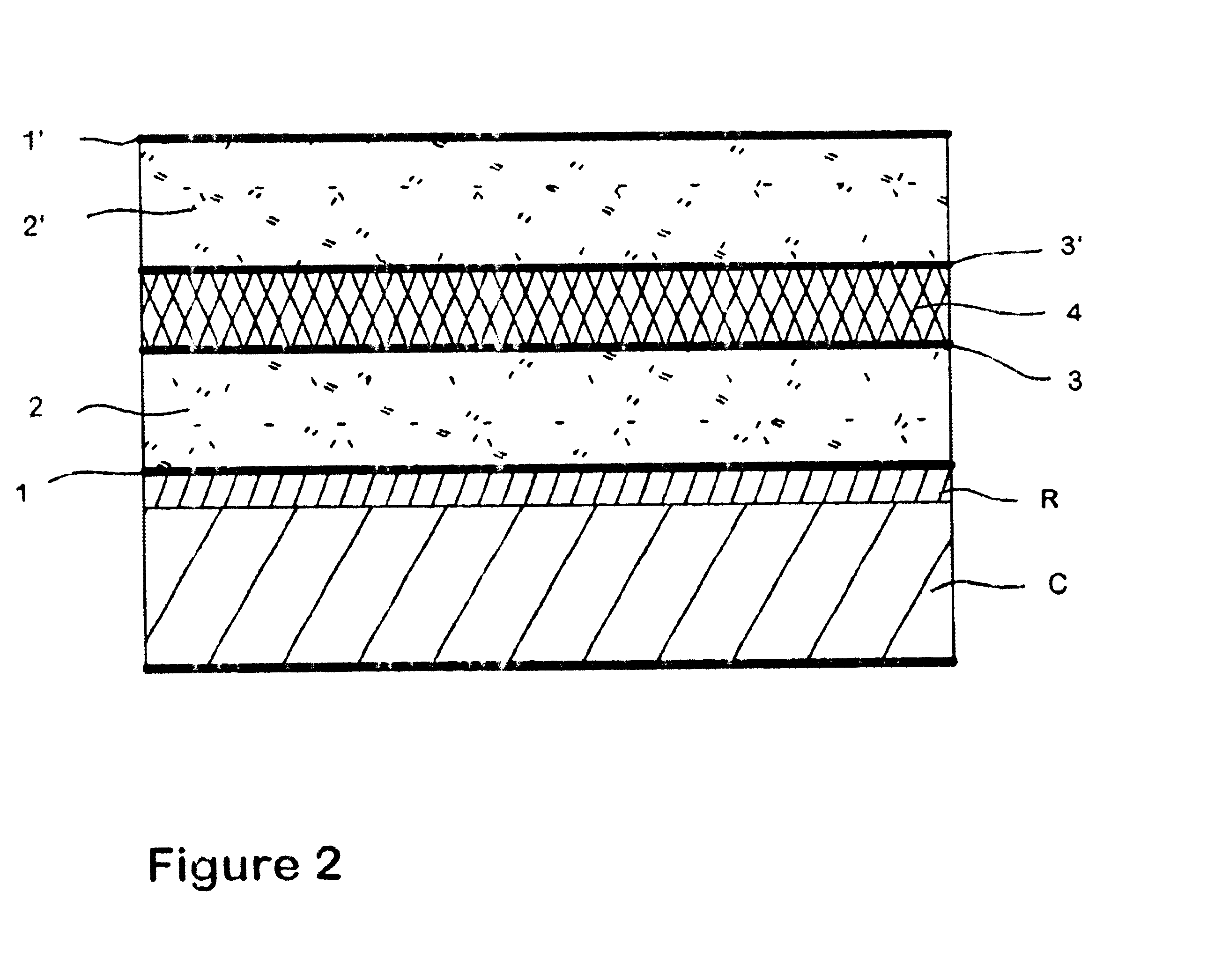
In the first preferred embodiment of a magnetic OVP, depicted in FIG. 2, the magnetic layer 4 is comprised within two totally reflector layers 3, 3′ of the OVP stack. In order to provide for optimal conditions of both, the optical and the magnetic function, the “standard” OVP layer sequence chromium / magnesium fluoride / aluminum is used to implement the optical function. The aluminum layer is “split in two”, in order to accommodate the magnetic functionality in its interior in the form of an additional layer of any desired magnetic element, alloy or compound.

On a release-coated R carrier foil C, a first absorber layer 1 of chromium is deposited, followed by a first dielectric layer 2 of magnesium fluoride and a first reflector layer 3 of aluminum. Then, the magnetic layer 4 of magnetic material is deposited, followed by a second reflector layer 3′ of aluminum. A second dielectric layer 2′ of magnesium fluoride and a second absorber layer 1′ of chromium are then deposited, to finish th...


PUM

PropertyMeasurementUnit
Interferenceaaaaaaaaaa
Lightaaaaaaaaaa
Magnetismaaaaaaaaaa

Abstract

The invention discloses magnetic OVP, said pigment consisting of thin-layer flakes having a basic metal-dielectric-metal structure to result in a viewing-angle dependent color appearance, and having, in addition to said viewing-angle dependent color appearance, incorporated magnetic properties, to make them distinguishable from OVP of similar appearance but not having said magnetic properties. The invention discloses as well methods for obtaining such pigments and the use of such pigments as security elements in inks, coatings and articles.

Description

FIELD OF THE INVENTIONThe present invention is in the field of optically variable pigments. In particular, it describes a magnetic thin film interference device, a method of making such a magnetic thin film interference device, a magnetic thin film interference pigment, a printing ink or coating composition, a security document and the use of such a magnetic thin film interference device, all according to the definition of the patent claims.BACKGROUND OF THE INVENTIONOptically variable devices of various types are used as an efficient anti-copy means on bank notes and security documents. A large part of the world-wide printed currency relies on such optically variable copy protection devices, and among these, features printed with optically variable ink (OVI™) have acquired a preeminent position since their first appearance on currency in 1987.Optically variable pigment (OVP) shows a viewing-angle dependent color appearance which cannot be reproduced by color copying equipment. Vari...

Claims


Application Information

Patent Timeline
IPC IPC(8): C09C1/00G02B5/22B32B7/00B42D15/10B32B7/02B42D15/00C09C1/62C09C3/06C09D5/23C09D5/29C09D201/00G02B5/28H01F10/14H01F10/16H01F10/20H01F41/16
CPCC09C1/0078G02B5/223C09C1/0015C01P2006/42Y10T428/12868C09C2200/1004C09C2200/1008C09C2200/303C09C2200/306C09C2200/308C09C2220/20Y10T428/31Y10T428/24942Y10T428/12535Y10T428/12986Y10T428/12465Y10T428/12806Y10T428/32G02B5/22
Inventor SETO, MYRONTILLER, THOMASMULLER, EDGARDESPLAND, CLAUDE-ALAIN
Owner SICPA HLDG SA
Why Eureka
Try Eureka