Eureka AIR delivers breakthrough ideas for toughest innovation challenges, trusted by R&D personnel around the world.

Organic light-emitting diode devices having reduced ambient-light reflection and method of making the same

Active Publication Date: 2005-04-05
AU OPTRONICS CORP
View PDF8 Cites 15 Cited by
  • Summary
  • Abstract
  • Description
  • Claims
  • Application Information

AI Technical Summary

Benefits of technology

The second objective of the present invention is to provide a method for adjusting the thickness of the organic layer and the transparent electrode, thereby reducing the ambient-light reflection for the OLED device.
In the first embodiment, the method comprises the following steps. Firstly, a metal reflective layer is formed on a provided substrate. Then a transparent anode, an organic layer, a translucent electron-injecting cathode, a buffer layer and a transparent electrode are sequentially deposited on the metal reflective layer. In order to reduce the affect of the ambient-light reflection, during the designated deposition procedure, adjusting one or both of the thickness of the organic layer and the transparent anode that the reflected lights generate destructive optical interference and improve the visually perceived contrast of the emitted light.
In the second embodiment of the present invention, different from the first embodiment, the metal anode is directly deposited on the substrate instead of depositing the metal reflective layer and the transparent anode thereon. By adjusting the thickness of the organic layer that the reflected lights generate destructive optical interference and improve the visually perceived contrast of the emitted light.

Problems solved by technology

By adjusting the thickness of the organic layer that the reflected lights generate destructive optical interference and improve the visually perceived contrast of the emitted light.

Method used


Image

  • Organic light-emitting diode devices having reduced ambient-light reflection and method of making the same
  • Organic light-emitting diode devices having reduced ambient-light reflection and method of making the same
  • Organic light-emitting diode devices having reduced ambient-light reflection and method of making the same

Examples


Embodiment Construction

The invention disclosed herein is the organic light-emitting diode device having reduced ambient-light reflection and method of making the same. In the following description, numerous details are set forth in order to provide a thorough understanding of the present invention. It will be appreciated by one skilled in the art that variations of these specific details are possible while still achieving the results of the present invention. In other instance, well-known components are not described in detail in order not to unnecessarily obscure the present invention.

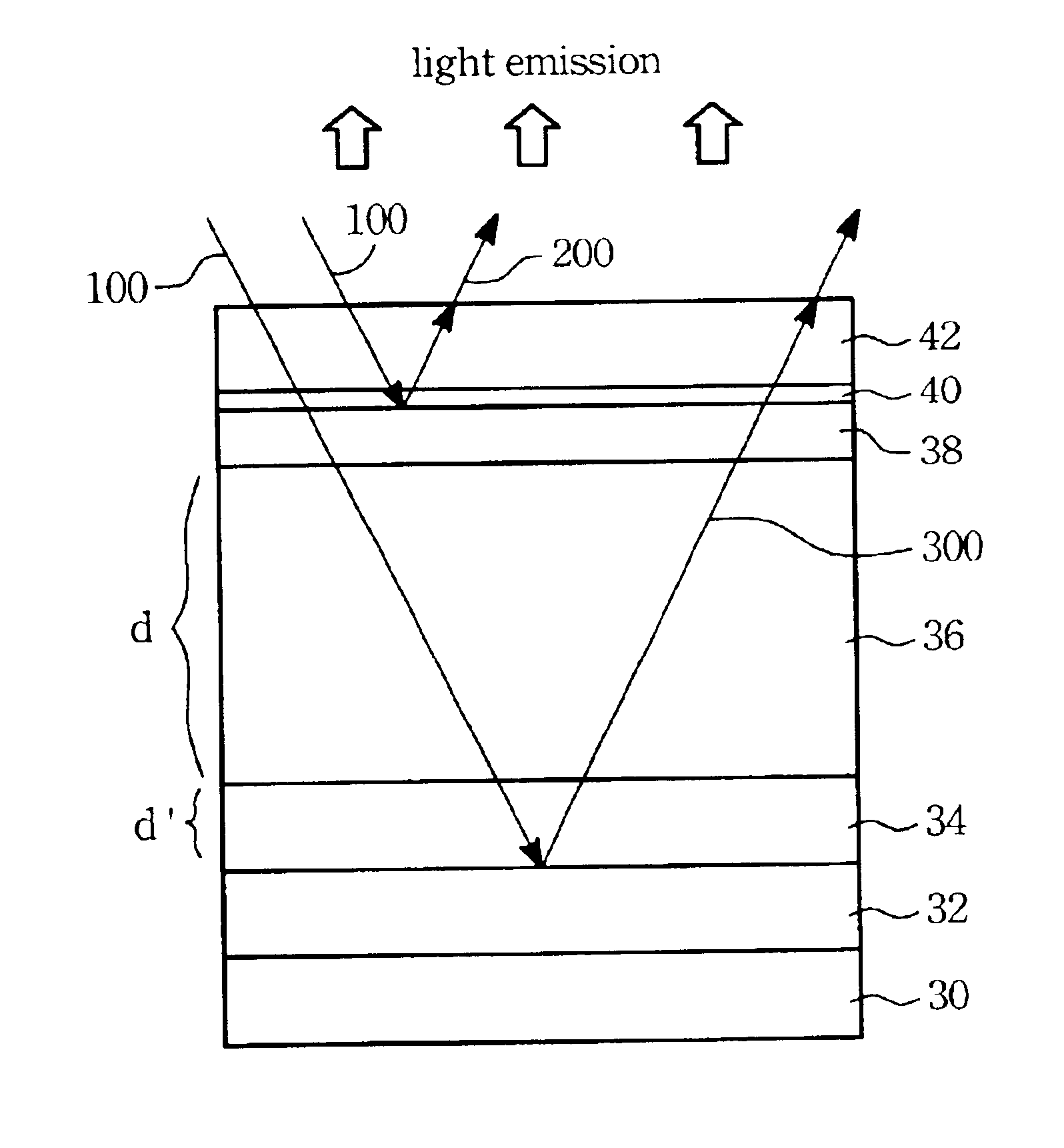
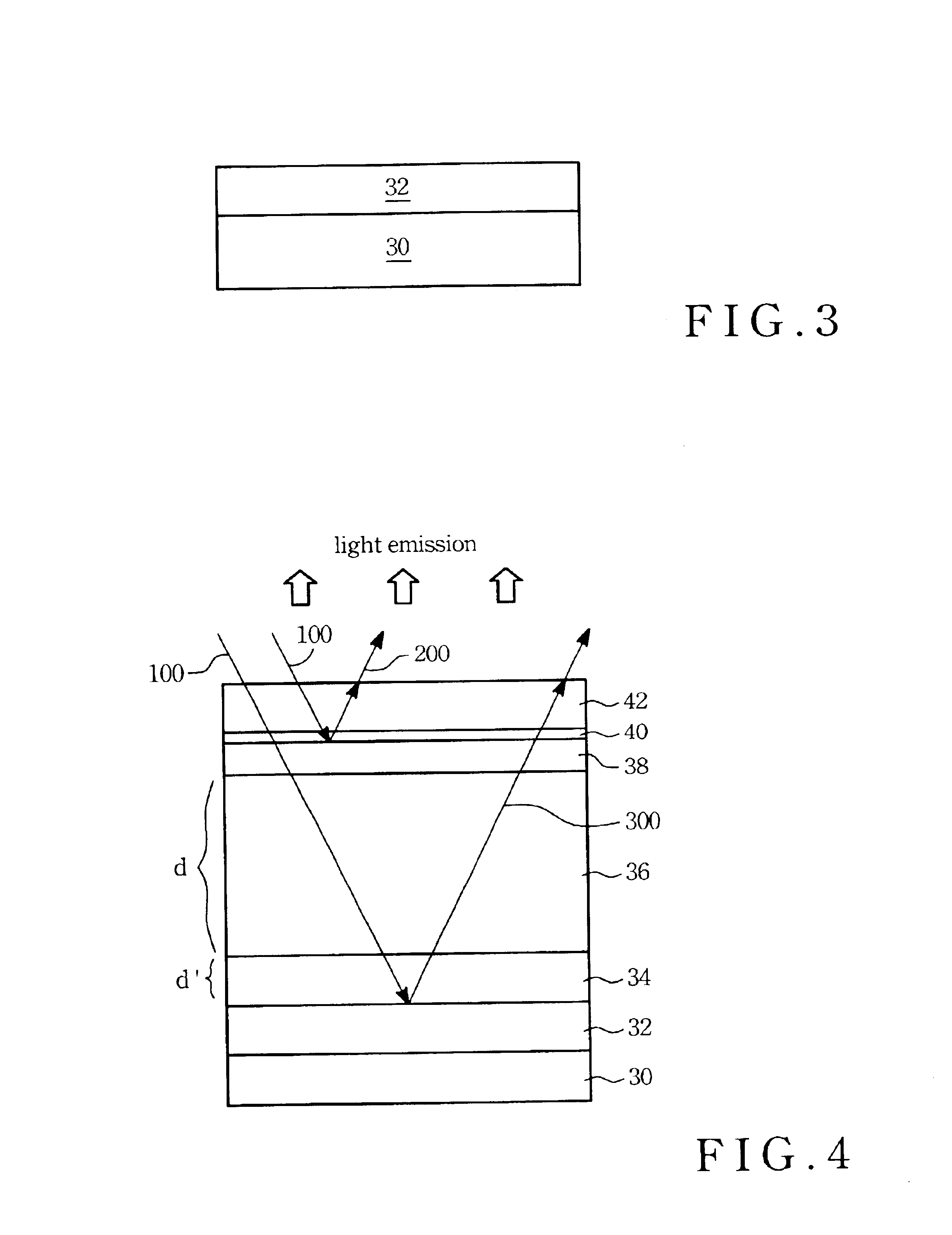
Referring to FIG. 4, in the first embodiment of the present invention the OLED device is made for reducing ambient-light reflection. As shown in FIG. 3, firstly, a substrate 30 is provided to form the OLED structure. Then, a metal reflective layer 32 is formed on the substrate 30 by performing a PVD or CVD procedure such as sputtering or evaporation. The aforementioned metal material can be chosen from a good conductor in e...


PUM


Abstract

A method of manufacturing an organic light-emitting device having reduced ambient-light reflection is disclosed. The method comprises the following steps. First, a metal reflective layer is formed on a provided substrate. Then a transparent anode, an organic layer, a translucent electron-injecting cathode, a buffer layer and a transparent electrode are sequentially deposited on the metal reflective layer. In order to reduce the affect of the ambient-light reflection, adjusting the thickness of the aforementioned layers that the reflected lights generate destructive optical interference and improve the visually perceived contrast of the emitted light.

Description

BACKGROUND OF THE INVENTION(1) Field of the InventionThe invention relates to the organic light-emitting diode devices, and more particularly to the organic light-emitting diode devices having reduced ambient-light reflection and methods for making the same.(2) Description of the Prior ArtOwing to high brightness, fast response speed, light weight, thin and small features, full color, no viewing angle differences, no need for an LCD back-light board and low electrical consumption, an organic light emitting diode display or organic electroluminescence display (OLED) takes the lead to substitute a twist nematic (TN) or a super twist nematic (STN) liquid crystal display. Further, it substitutes for a small-sized thin-film transistor (TFT) LCD to become a new display material of fabricating portable information products, cell phones, personal digital assistant (PDA) and notebook.Referring to FIG. 1, an organic light-emitting diode (OLED), also referred to as an organic electroluminescen...

Claims


Application Information

Patent Timeline
IPC IPC(8): H01L51/52H01L51/50H01L33/00H01L33/44
CPCH01L51/5281H01L33/44H10K50/86
Inventor KO, CHUNG-WEN
Owner AU OPTRONICS CORP
Why Eureka
Eureka Blog
Learn More