
Method and apparatus for high speed bus having adjustable, symmetrical, edge-rate controlled, waveforms

Inactive Publication Date: 2005-04-05
VALTRUS INNOVATIONS LTD +1
View PDF5 Cites 8 Cited by
  • Summary
  • Abstract
  • Description
  • Claims
  • Application Information

AI Technical Summary

Benefits of technology

[0012]A high-speed bussing system utilizes waveforms having controlled edge rates to minimize harmonics while maintaining rapid transitions. The waveforms have smoothe

Problems solved by technology

Common problems in bussing include reflections on, and crosstalk between, lines of a bus.
Reflections and crosstalk can degrade the integrity of signals on the bus, leading to errors.
This is because reflected signals have delay dependent upon these lengths.
Integrated circuit design and fabrication not only is very expensive, but design times are often much longer than system board design times. Integrated circuits may be used on multiple, somewhat different, system boards.

Method used


Image

  • Method and apparatus for high speed bus having adjustable, symmetrical, edge-rate controlled, waveforms
  • Method and apparatus for high speed bus having adjustable, symmetrical, edge-rate controlled, waveforms
  • Method and apparatus for high speed bus having adjustable, symmetrical, edge-rate controlled, waveforms

Examples


Embodiment Construction

rable in a system for determining a bus driver configuration to maximize noise margin;

[0024]FIG. 6, a block diagram illustrating a computer system embodying a multidrop bus;

[0025]FIG. 7, an illustration of a trapezoidal waveform;

[0026]FIG. 8, a sketch of a gated sinusoidal waveform;

[0027]FIG. 9, a sketch of a waveform derived by blending gated sinusoid and trapezoidal waveforms; and

[0028]FIG. 10, a schematic of the pulldown half of a driver capable of generating edge waveforms determined by individual sizing of devices.

DETAILED DESCRIPTION OF THE EMBODIMENTS

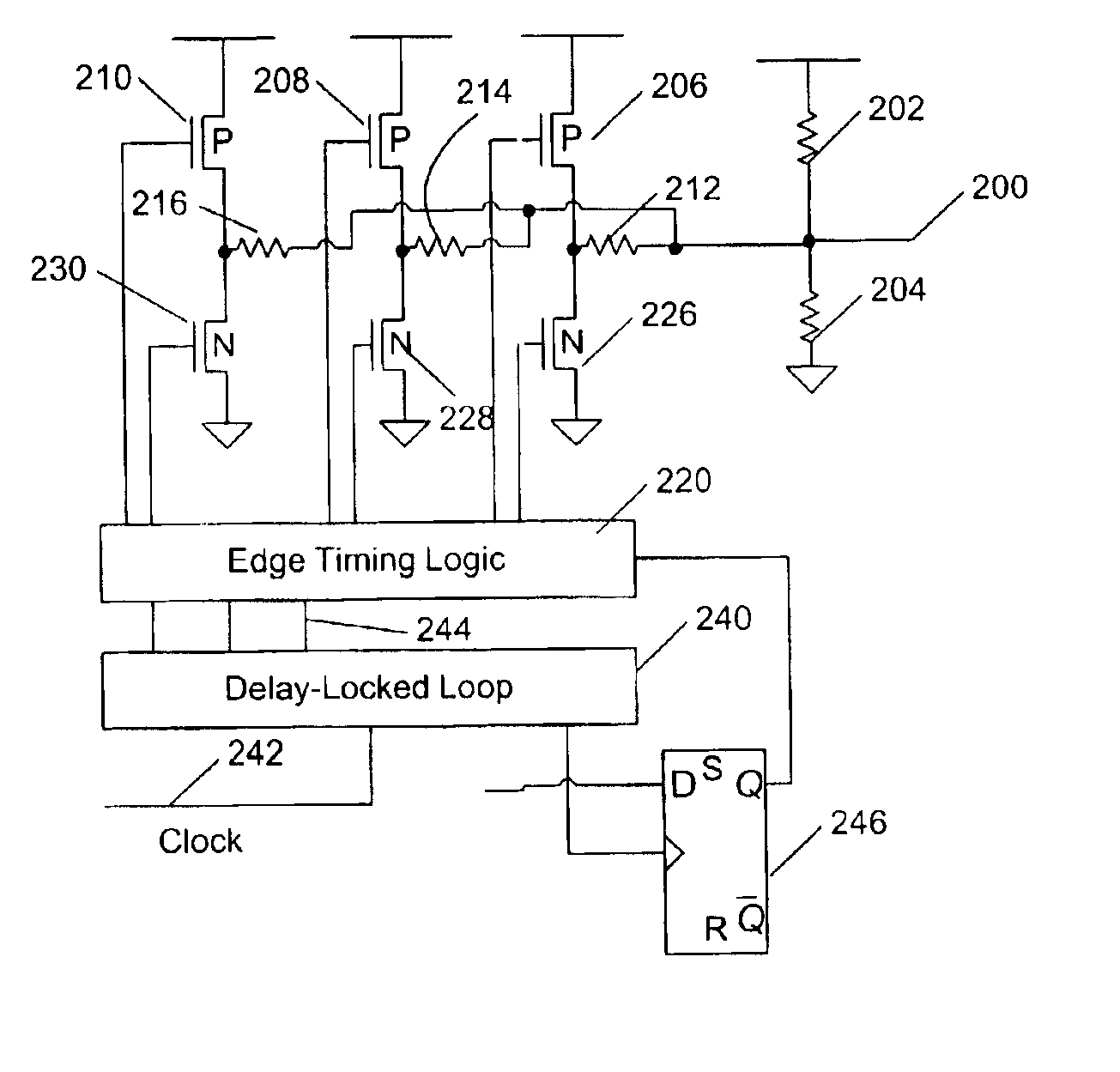
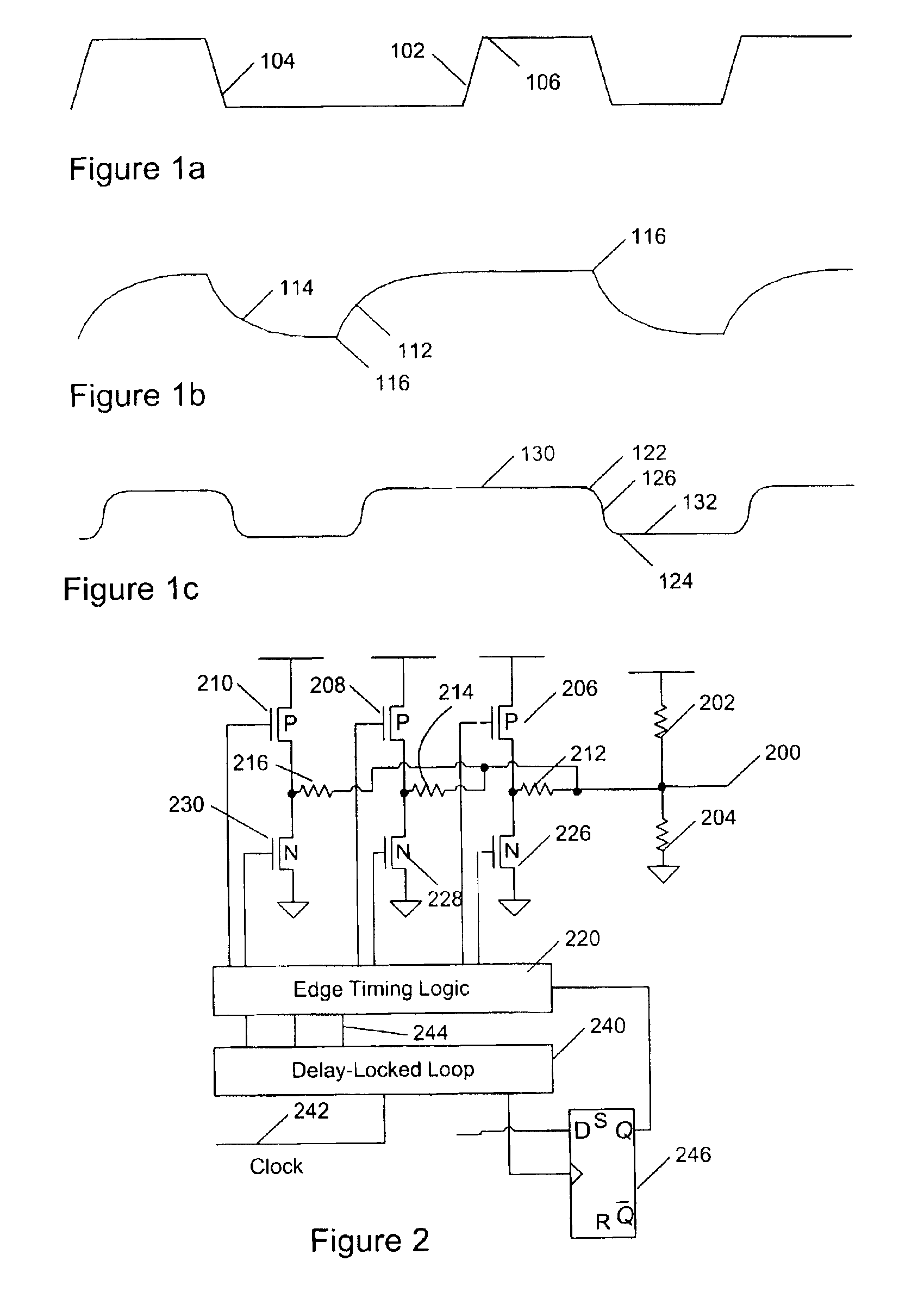
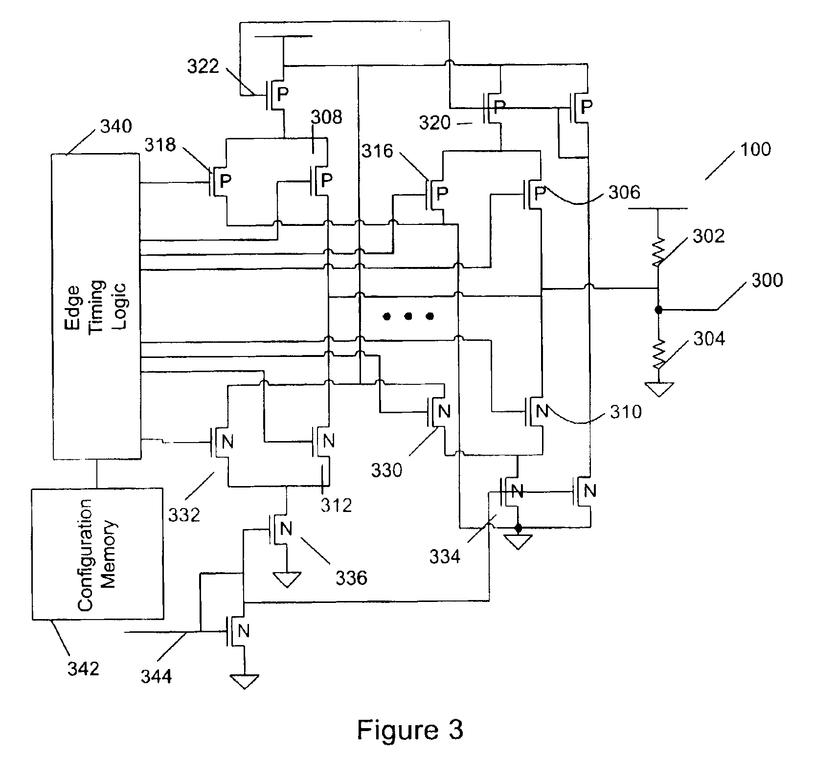
[0029]A waveform (FIG. 1a) of a typical bus interconnecting CMOS (Complimentary Metal Oxide Semiconductor) integrated circuits has fairly steep rising 102 and falling 104 edges. The waveform has fairly sharp transitions 106 between rising or falling edges and stable high or low periods. These steep edges 102, 104 and sharp transitions 106 are characterized by considerable energy in high harmonics, such that reflections and crosst...


PUM


Abstract

A method of enhancing noise margin on digital signal lines of a system includes steps of evaluating impedances and lengths of the digital signal lines. Resonances of each digital signal line are determined, and target waveforms for each digital signal line optimized for noise margin are determined. A configuration is generated for a programmable device driver to configure the device driver to generate the waveform optimized for noise margin. An alternative embodiment selects waveforms, and corresponding configurations, from a group of possible waveforms at boot time to ensure that data is transferred with optimum noise margins. Also claimed is apparatus embodying bus drivers capable of driving a bus with a waveform approximating blended trapezoidal and sinusoidal edge shapes, this waveform being optimum for noise margin in certain systems having multidrop busses.

Description

FIELD OF THE INVENTION[0002]The invention relates to apparatus for high speed bussing. In particular, the invention relates to tuning waveforms for high speed bussing to enhance signal integrity.BACKGROUND OF THE INVENTION[0003]Bussing is commonly used to interconnect various elements of a computer system. Typically each bus services two, three, or more devices. Single-ended bussing typically has a single set of data lines, one for each bit, with associated reference grounds, control, and power lines, all connecting to each device on the bus. Differential bussing typically has a differential pair of lines for each data bit, with associated reference grounds, differential pairs of control lines, and power lines, all connecting to each device on the bus.[0004]Repetitive signals, including bus waveforms can be represented as a superposition of sine waves. A typical bus waveform has frequency components at a fundamental frequency equal to one-half the maximum transition rate of the bus,...

Claims


Application Information

Patent Timeline
IPC IPC(8): H03K17/16
CPCH03K17/167H03K17/164
Inventor MARSHALL, DAVID JOHNBARNES, PHILIP L.THAYER, LARRY JAY
Owner VALTRUS INNOVATIONS LTD
Learn More