Accelerated commutation for passive clamp isolated boost converters

a passive clamp and boost converter technology, applied in the direction of electric variable regulation, process and machine control, instruments, etc., can solve the problems of severe limitation in a low voltage, inability to meet current conditions, and high implementation cost of technology, so as to achieve efficient and cost-effective

Inactive Publication Date: 2005-04-05
VIRGINIA TECH INTPROP INC
View PDF7 Cites 68 Cited by
  • Summary
  • Abstract
  • Description
  • Claims
  • Application Information

AI Technical Summary

Benefits of technology

Accordingly, an object of the present invention is to provide an efficient and cost effective high power bidirectional DC / DC converter that can withstand the vigorous environment of an automobile.
In one aspect a method and system to accelerate commutation for passive-clamped isolated high power boost converters includes a primary circuit having at least one pair of diagonal controllers (such as switched diodes); a secondary circuit comprising at least two controllers (such as switched diodes); a one directional or bidirectional transformer connected to the primary circuit and the secondary circuit. The primary circuit may also having a snubber circuit comprising a clamping diode, a clamping capacitor and an energy dissipater such as a resistor. In another aspect a small buck converter can replace the resistor to increase efficiency. The clamping diode can be electrically coupled in a “bridge,”“push-pull,” or “L” configuration. The commutation of the present invention protects the primary circuit switches from voltage spikes in a boost mode.
The present invention shorts the secondary circuit by turning on at least two switches in the secondary circuit simultaneously for a minimal calibratable period (for example, 2 microseconds) while a pair of switch devices in the primary circuit turn off, whereby the primary circuit current can be transferred to the secondary circuit quickly and reduce a voltage spike due to primary current and transformer leakage interaction.
The present invention also has a means to allow a smooth transition between a choke (inductor) current and a transformer primary current. Primary current increases linearly through the snubber circuit during switching conditions, thus protecting the primary circuit controllers.

Problems solved by technology

Unfortunately, this is not presently the case.
Unfortunately, the use of a simple prior art passive-clamped snubber circuit results in severe limitation in a low voltage (e.g., 12V), high current (e.g., hundreds of amperes) application due to significant power loss, although it is a simple approach widely used to resolve the voltage spike issue.
This recycles the dissipated energy and improves efficiency, but this technology is expensive to implement.

Method used


Image

  • Accelerated commutation for passive clamp isolated boost converters
  • Accelerated commutation for passive clamp isolated boost converters
  • Accelerated commutation for passive clamp isolated boost converters

Examples


Embodiment Construction

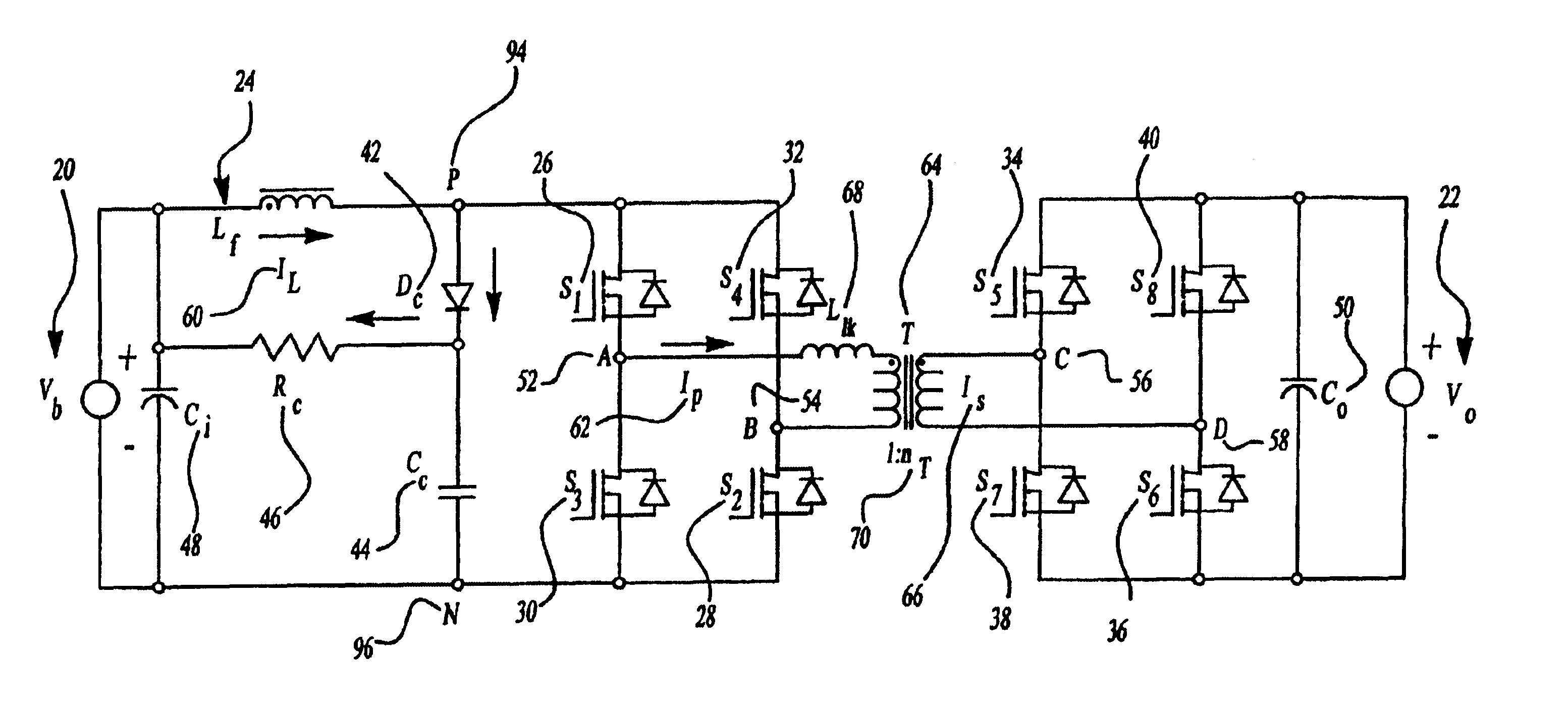
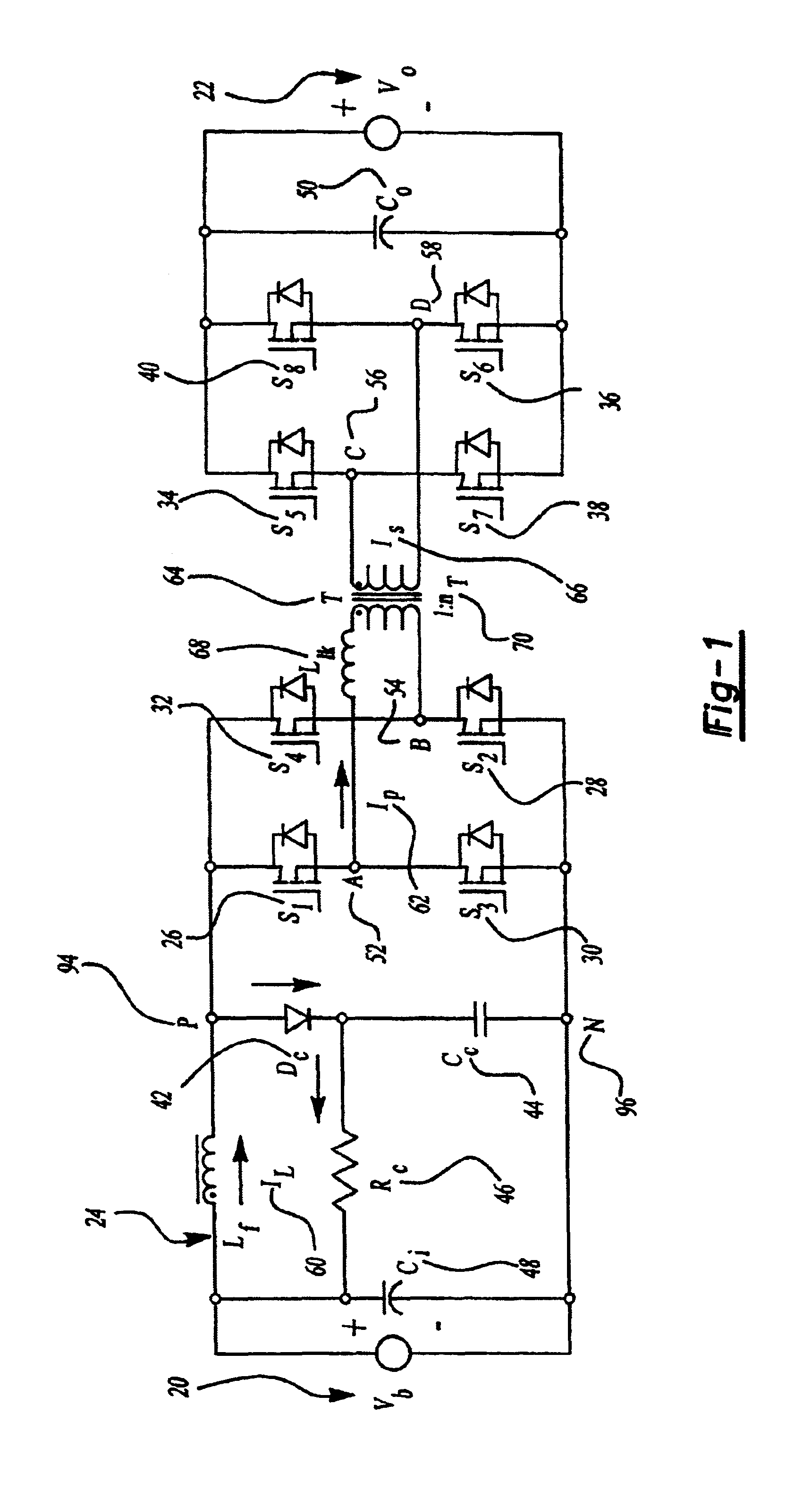
The present invention relates generally to a DC / DC converter and specifically to a system and method to accelerate commutation for a passive clamp isolated boost for a high power bidirectional DC / DC converter. For the present application, high power could be defined as greater than 1 kW power.

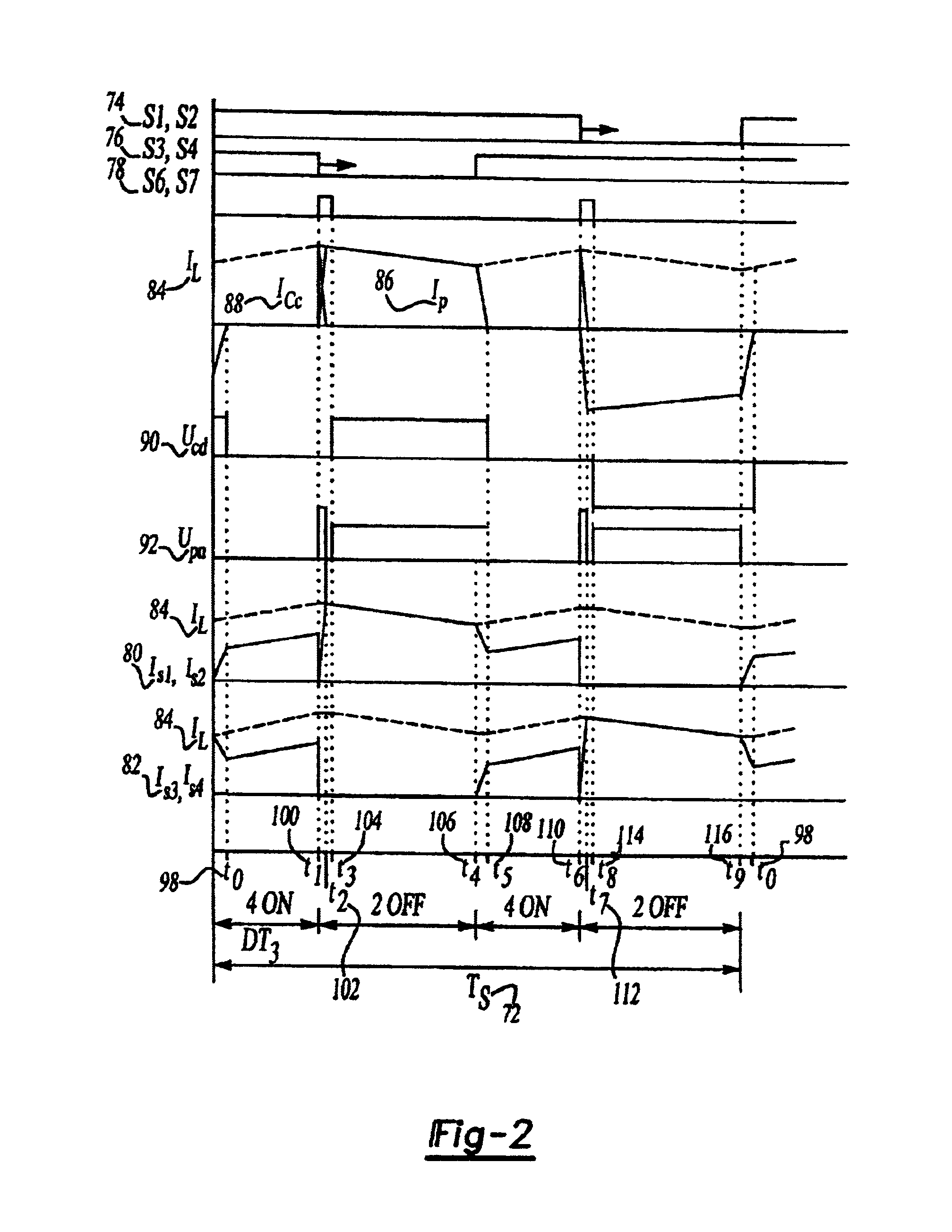
Generally, the operation of inductive storing converters is based on energy transfer cycles. This includes a period of accumulation of magnetic energy in an inductive device (such as an inductor or transformer) through a circuit, followed by a period of restitution of this energy in a load (such as a typical 12V load in a car) through another circuit.

The present invention relates in particular to a DC / DC converter. This converter can be bidirectional and transform energy from primary to secondary circuits and from the secondary to primary circuits through a transformer. The primary circuit comprises at least one pair of switches such as switched diodes and the secondary circuit has two pairs of...


PUM


Abstract

An efficient and cost effective bidirectional DC / DC converter reduces switch voltage stress via accelerated commutation allowing use of a low-cost passive clamp circuit in boost mode. The converter includes a primary circuit, transformer and secondary circuit. The primary circuit takes the form of a “full bridge converter,” a “push-pull converter,” or an “L-type converter.”. The primary circuit may include a dissipator such as a snubber circuit or small buck converter. A secondary side of the transformer is momentarily shorted by the secondary circuit by, for example, turning on at least two switches in the secondary circuit simultaneously for a minimal calibratable period when a pair of primary circuit controllers turn off to protect the primary circuit switches from voltage spikes during switching conditions.

Description

BACKGROUND OF THE INVENTION1. Field of the InventionThe present invention relates generally to a DC / DC converter.2. Discussion of the Prior ArtThe need to reduce fossil fuel consumption and emissions in automobiles and other vehicles predominately powered by internal combustion engines (ICEs) is well known. Vehicles powered by electric motors attempt to address these needs.Typically, a vehicle propelled by an electric motor can use batteries or fuel cells to generate the necessary current. Fuel cells generate electrical power through an electrochemical reaction of a fuel and oxidant, such as hydrogen and oxygen. Water is the product of the electrochemical reaction in a fuel cell utilizing hydrogen and oxygen, a product that is easily disposed. See generally, U.S. Pat. No. 5,991,670 to Mufford.The desirability of using electric motors to propel a vehicle is clear. There is great potential for reducing vehicle fuel consumption and emissions with no appreciable loss of vehicle performa...

Claims


Application Information

Patent Timeline
Patent Type & Authority Patents(United States)
IPC IPC(8): H02M3/337H02M3/335H02M3/24H02M1/34
CPCH02M1/34H02M3/33584H02M3/33592H02M3/337Y02B70/1491H02M2001/342H02M2001/348Y02B70/1475Y02B70/10H02M1/342H02M1/348H02M3/33573
Inventor ZHU, LIZHILAI, JIH-SHENGLEE, FRED C.
Owner VIRGINIA TECH INTPROP INC
Why Eureka
Try Eureka