Device for heating gas from a thin layer of nuclear fuel, and space engine incorporating such device

a technology of nuclear fuel and heating gas, which is applied in the direction of nuclear elements, machines/engines, greenhouse gas reduction, etc., can solve the problems of limited mechanical strength, large amount of energy potentially available through fission process, and temperature of propellant gas

Inactive Publication Date: 2005-04-05
ENTE PER LE NUOVE TECH LENERGIA E LAMBIENTE ENEA
View PDF21 Cites 13 Cited by
  • Summary
  • Abstract
  • Description
  • Claims
  • Application Information

AI Technical Summary

Benefits of technology

In a typical embodiment, the fissile material coating has a fissile content lower than 10 mg/cm2, preferably in the range

Problems solved by technology

To ensure the heat flow from the fuel to the propellant gas, the temperature of the propellant gas must be somewhat less than the operating temperature of the fuel, in turn limited by the mechanical strength and the stability of the fuel rods at high temperatures.
The vast amount of energy potentially available through the fission process remains largely untapped due to (1) size constraints associated with the minimum critical mass required to sustain the fission chain reaction and (2) the difficulty of extracting heat at sufficiently high temperatures from the reactor.
The NERVA engine is basically a naked fast reactor, which represents a serious drawback of nuclear engines for space propulsion.
In addition, the neutron leakage will also hamper the simultaneous operation of several NERVA engines nearby, as in the above-mentioned report.
The coupled control system for mutually interfering reactors is, in

Method used


Image

  • Device for heating gas from a thin layer of nuclear fuel, and space engine incorporating such device
  • Device for heating gas from a thin layer of nuclear fuel, and space engine incorporating such device
  • Device for heating gas from a thin layer of nuclear fuel, and space engine incorporating such device

Examples


Embodiment Construction

1.—Fission Fragment Heating

The well known neutron induced fission reaction is the preferred source of nuclear energy because of its high energy yield and its ability of sustaining a chain reaction based on neutrons. In this reaction, the initial nucleus is split into two fission fragments (FF) and a number of neutrons (≧2) which are necessary to continue the chain reaction. The average energy sharing in a typical fission reaction is such that a major proportion—namely 168 MeV / 191 MeV=88%—of the usable energy (neutrinos are excluded) is produced in the form of kinetic energy by the pair of FF. The fragments of father nucleus being split away beyond the range of the (attractive) nuclear forces, energy is produced by the strong electrostatic repulsion between the two fragments—the rest being de-excitation of the nuclear levels with gamma and neutron emission, possibly followed by β de-excitation.

FF travel a very short way in the fissionable fuel, delivering energy in the form of heat i...


PUM


Abstract

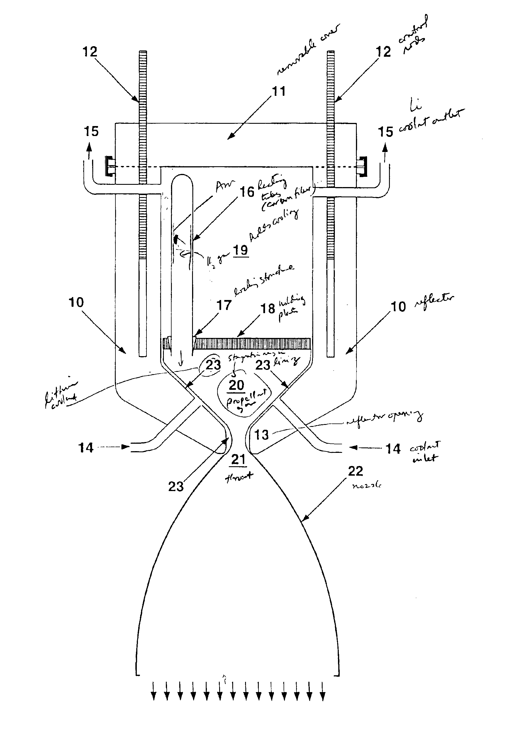
A gas, e.g. hydrogen, at relatively low pressure is directly heated by the fission fragments (FF) emitted by a thin layer of fissile material, e.g. 242mAm, deposited on the inner wall of a chamber which is kept cooled at a typical temperature of about 1,000/1,500 K. The gas is preferably emitted as capillary flow from the walls of cylindrical tubes. Its temperature progressively increases until it reaches an equilibrium value of the order of 9,500 K, at which point FF heating and radiative cooling balance. With a relatively modest surface power density at the foil of 200 W/cm2, the specific, volume-averaged power given to the H gas may be as large as 0.66 MWatt/g. Heating powers up to megawatts for each gram of gas are therefore feasible with acceptable foil surface heating. The gas heating method can be used in rocket engines for deep space propulsion.

Description

BACKGROUND OF THE INVENTIONThe present invention relates to the use of nuclear fission to heat gases. It has applications in the field of deep space rocket propulsion, in particular.If nuclear energy is presently competing with other methods on Earth, for deep space travel it has unique features which make it practically indispensable in order to realistically attain the long range goals of a manned exploration of Mars, of the outer planets' satellites and of the Asteroids.Neutron induced fission is the preferred nuclear reaction for practical energy production, because of (1) its remarkable energetic yield (≈200 MeV) and (2) its ability of sustaining the reaction with the secondary neutrons.The present state of the art of nuclear space propulsion, is represented for instance by the NERVA design (see “Nuclear thermal rockets: next step to space”, Aerospace America, June 1989, pages 16-29; or R. W. Bussard, et al. “Nuclear Rocket Propulsion”, McGraw-Hill, New York, 1958). In the NERV...

Claims


Application Information

Patent Timeline
IPC IPC(8): B64G1/40B64G1/22G21D5/00G21D5/02G21C1/00
CPCB64G1/408G21D5/02G21Y2002/203Y10S376/909G21Y2004/30G21Y2004/40G21Y2002/304Y02E30/00
Inventor RUBBIA, CARLO
Owner ENTE PER LE NUOVE TECH LENERGIA E LAMBIENTE ENEA
Why Eureka
Try Eureka