Eureka AIR delivers breakthrough ideas for toughest innovation challenges, trusted by R&D personnel around the world.

Wireless local area network system, fault recovery method, and recording medium stored therein a computer program executing the fault recovery process

Inactive Publication Date: 2005-04-05
NEC PLATFORMS LTD
View PDF11 Cites 52 Cited by
  • Summary
  • Abstract
  • Description
  • Claims
  • Application Information

AI Technical Summary

Benefits of technology

An object of the present invention is to provide a wireless LAN system that prevents throughput from being decreased even when an access point fails, a fault recovery method, and a recording medium storing therein a computer program executing the fault recovery process.
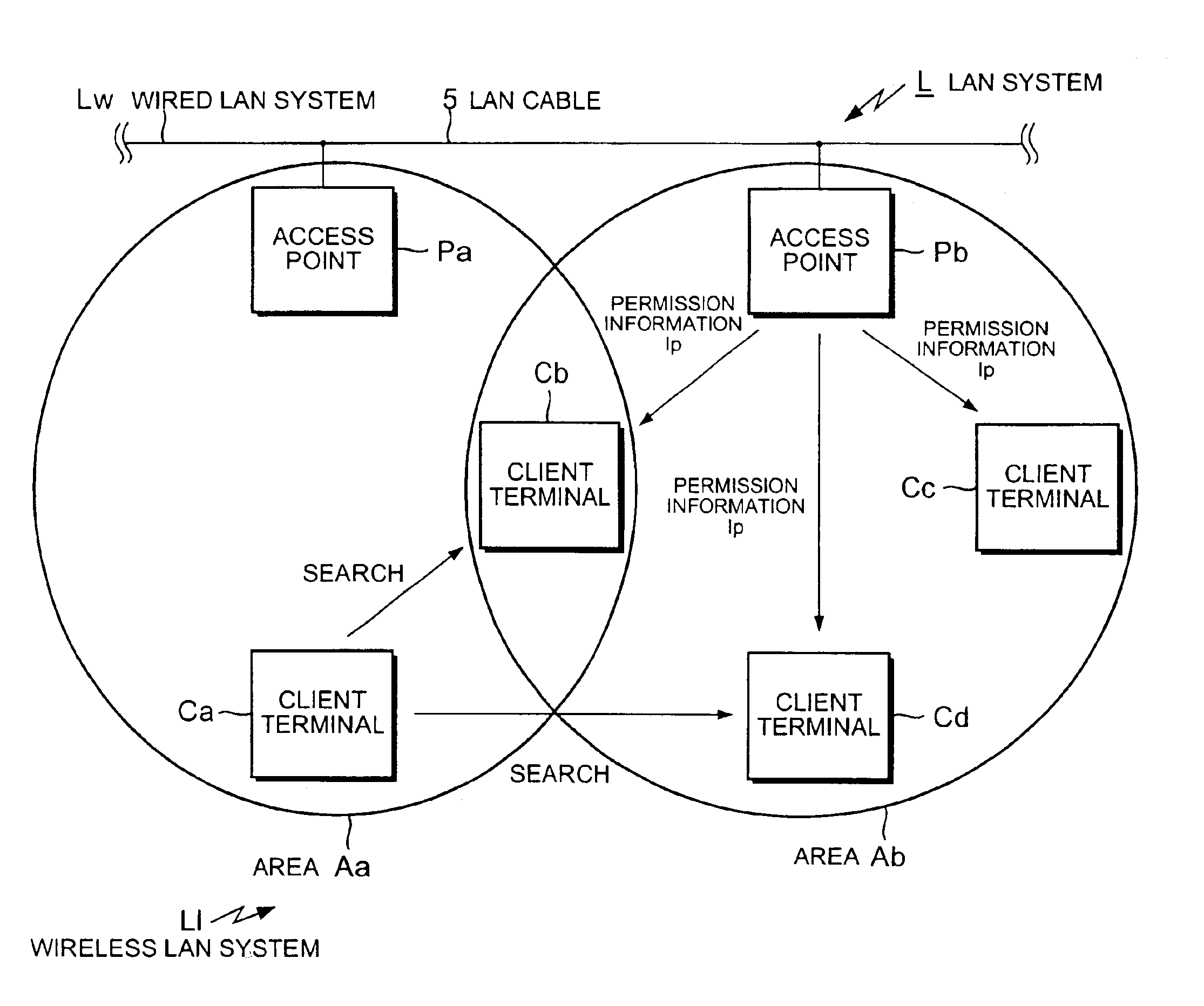
When a fault occurs in an access point, a client terminal connected to this access point is disconnected. Instead of connecting the disconnected client terminal to another access point as in the conventional example, the system according to the present invention connects the client terminal to another client terminal. And, through this another client terminal, the disconnected client terminal connects to another access point. This prevents the load from being concentrated at another access point.

Problems solved by technology

However, the above processing has the problems described below.
This increases the radio wave interference around the client terminal Ca and therefore decreases the throughput of the whole LAN system L.
This processing has some problems with the client terminal Ca being battery-powered.
For example, this processing consumes more battery power for communication and therefore shortens battery life.
And, the increase in power consumption causes a quickly decrease in the power voltage, sometimes suddenly disconnecting the power of the portable information terminal and thus destroying data due to a communication interruption.
This increases the radio wave interference and therefore decreases the throughput of the whole LAN system.

Method used


Image

  • Wireless local area network system, fault recovery method, and recording medium stored therein a computer program executing the fault recovery process
  • Wireless local area network system, fault recovery method, and recording medium stored therein a computer program executing the fault recovery process
  • Wireless local area network system, fault recovery method, and recording medium stored therein a computer program executing the fault recovery process

Examples


Embodiment Construction

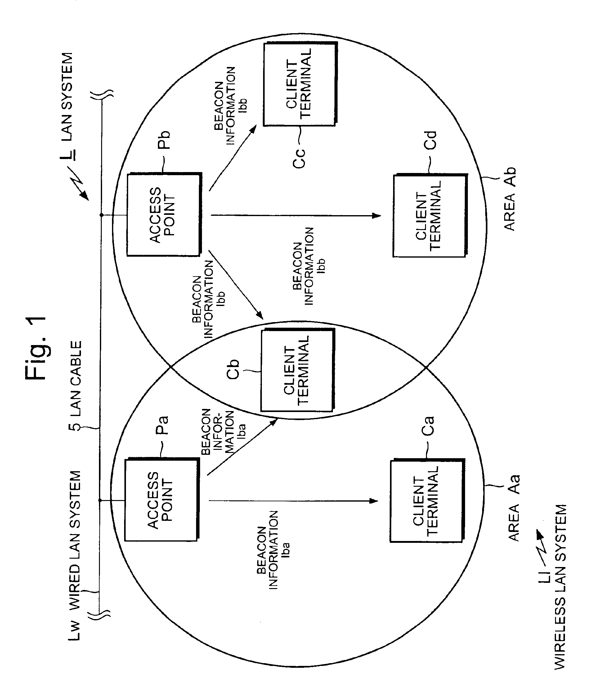
FIG. 1 is a block diagram showing a wireless LAN system in an embodiment of the present invention.

A wireless LAN system Ll, shown in FIG. 1, consists of access points Pa and Pb that are bridges to a wired LAN system Lw and client terminals Ca-Cd that are wireless communication terminals communicating with these access points Pa and Pb.

This wireless LAN system Ll uses Carrier Sense Multiple Access with Collision Avoidance (CSMA / CA) as the communication protocol. Note that any number of the access points Pa and Pb and the client terminals Ca-Cd may be used.

On the other hand, the wired LAN system Lw consists of the access points Pa and Pb, which are bridges to the wireless LAN system Ll, and a LAN cable 5 which is, for example, an Ethernet cable connecting the access points Pa and Pb. This wired LAN system Lw uses Carrier Sense Multiple Access with Collision Detection (CSMA / CD) as the communication protocol.

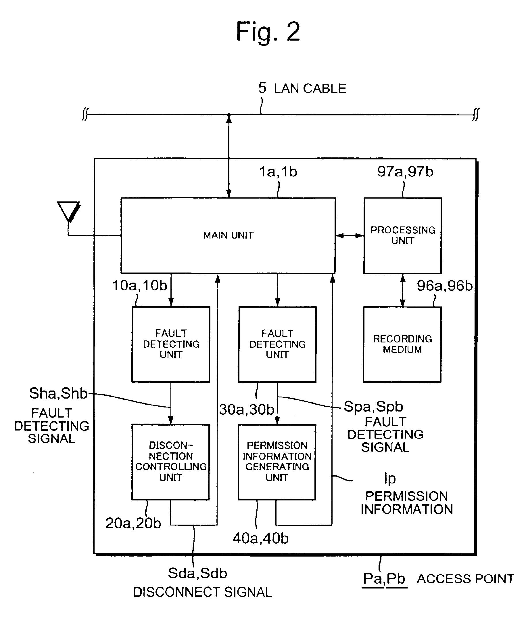
FIG. 2 is a block diagram of an access point of the wireless LAN system accordi...


PUM


Abstract

The present invention provides a wireless local area network (LAN) system preventing throughput from being decreased even when a fault occurs in an access point, a fault recovery method, and a recording medium stored therein a computer program for executing the fault recovering process. The method for use in a wireless local area network system comprising a plurality of access points and a plurality of client terminals, the method comprising the steps of: detecting, by each of the access points, whether a fault occurs on each of the access points itself; disconnecting, by the access point which has detected the fault, the client terminal connected thereto; searching for, by the disconnected client terminal, another of the client terminals to which the disconnected client terminal is to be connected; and connecting the disconnected client terminal to the searched client terminal.

Description

BACKGROUND OF THE INVENTION1. Field of the InventionThe present invention relates to a wireless local area network (LAN) system, a fault recovery method, and a recording medium stored therein a computer program for executing the fault recovering process. More particularly, the present invention relates to a technology for preventing the throughput of the whole LAN system from being decreased even when a fault occurs in an access point.2. Description of the Prior ArtConventionally, there has been a wireless local area network (LAN) system connected to a wired LAN and many wireless terminals.Japanese Patent Laid-Open Publication No. Hei 7-312597 (disclosed in Japan on Nov. 28, 1995) discloses a wireless LAN system that prevents packets from being lost. This technology will be described below as a first conventional example.FIG. 10 is a block diagram showing the wireless LAN system according to the first conventional example. A wireless LAN system 110, shown in FIG. 10, consists of a c...

Claims


Application Information

Patent Timeline
IPC IPC(8): G06F11/00G06F13/00H04B7/26H04B7/15H04L12/26H04L12/28H04L12/24H04Q7/38H04W24/04H04W76/02H04W84/12H04W84/22H04W88/04H04W88/08
CPCH04W24/04H04L41/0659H04W76/028H04W88/04H04W88/08H04W84/12H04W76/19
Inventor SHIMONO, FUMIHISA
Owner NEC PLATFORMS LTD
Why Eureka
Eureka Blog
Learn More