Hub member and shaft journal assembly and method

a technology of hub member and shaft, which is applied in the direction of shafts, couplings, forging hammers, etc., can solve the problems of disadvantageous influence of deformation processes on the dimensional accuracy of the respective other surfaces to be deformed, and achieve the effect of reducing the amount of energy and increasing the degree of accuracy

Inactive Publication Date: 2005-04-12
GKN AUTOMOTIVE GMBH
View PDF8 Cites 10 Cited by
  • Summary
  • Abstract
  • Description
  • Claims
  • Application Information

AI Technical Summary

Benefits of technology

It is therefore an object of the present invention to provide a method of producing an inner joint part of the initially mentioned type, which permits production with a reduced amount of energy and a greater degree of accuracy. The present invention provides a method involving process stages wherein a blank with largely finish-formed ball tracks is produced by non-chip-forming deformation; and wherein, at the blank, outer surfaces and a smooth through-aperture are finish-turned. The method also provides that, during simultaneous working stages, the ball tracks are calibrated by non-chip-forming deformation, and the inner toothing in the through-aperture is produced by pressing or profile slotting in a non-chip-forming way by a mandrel.
Because the shaft toothing is produced on a continuous through-aperture, the radial deformation rate is reduced. The substantially simultaneously performed calibration of the ball tracks by radial mechanical deformation and radial mechanical holding assures that neither of the two deformation processes has a disadvantageous affect on the dimensional accuracy of the respective other surfaces to be deformed. In other words, the production of the inner toothing does not lead to inaccurate track dimensions and the calibration of the ball tracks does not adversely affect the finish-dimensions of the inner toothing. In this way, subsequent machining can be avoided and a substantially higher degree of dimensional accuracy can be observed at the inner toothing and at the ball tracks. It is desirable that the inner joint part beheld in the clamping device, of the calibrating tool until the production of the inner toothing is complete.
According to another method of the above-mentioned type, during calibrating and slotting, a workpiece holding device for the hub member serves as an axial stop for the tool used for profile slotting. In this way, the workpiece holding device becomes the reference and stop face for the workpiece on the one hand, and for the tool for producing the inner toothing on the other hand. This permits the toothing run-out to be produced with the greatest precision regarding its axial position in the workpiece.
An inventive device for carrying out the present method comprises a base plate on to which an inner joint part can be placed and on which there is supported a calibrating tool which can be fed in radially and which is divided into at least three parts, a mandrel which can be fed in axially and which is arranged coaxially relative to the calibrating tool and comprises approximately the diameter of the through-aperture and, close to its lower end, a forming crown of a short length for producing the inner toothing. It is thus possible to press the inner toothing without generating any adverse effects on the ball track shape. To be able to set the accurate position of the toothing run-out, the present invention also provides that the mandrel is lowered until it stops against the base plate and that the forming crown is arranged at a predetermined distance from the lower end of the mandrel. To further improve the accuracy of the toothing, the forming crown comprises in both axial directions pointing forming wedges.

Problems solved by technology

The substantially simultaneously performed calibration of the ball tracks by radial mechanical deformation and radial mechanical holding assures that neither of the two deformation processes has a disadvantageous affect on the dimensional accuracy of the respective other surfaces to be deformed.

Method used


Image

  • Hub member and shaft journal assembly and method
  • Hub member and shaft journal assembly and method
  • Hub member and shaft journal assembly and method

Examples


Embodiment Construction

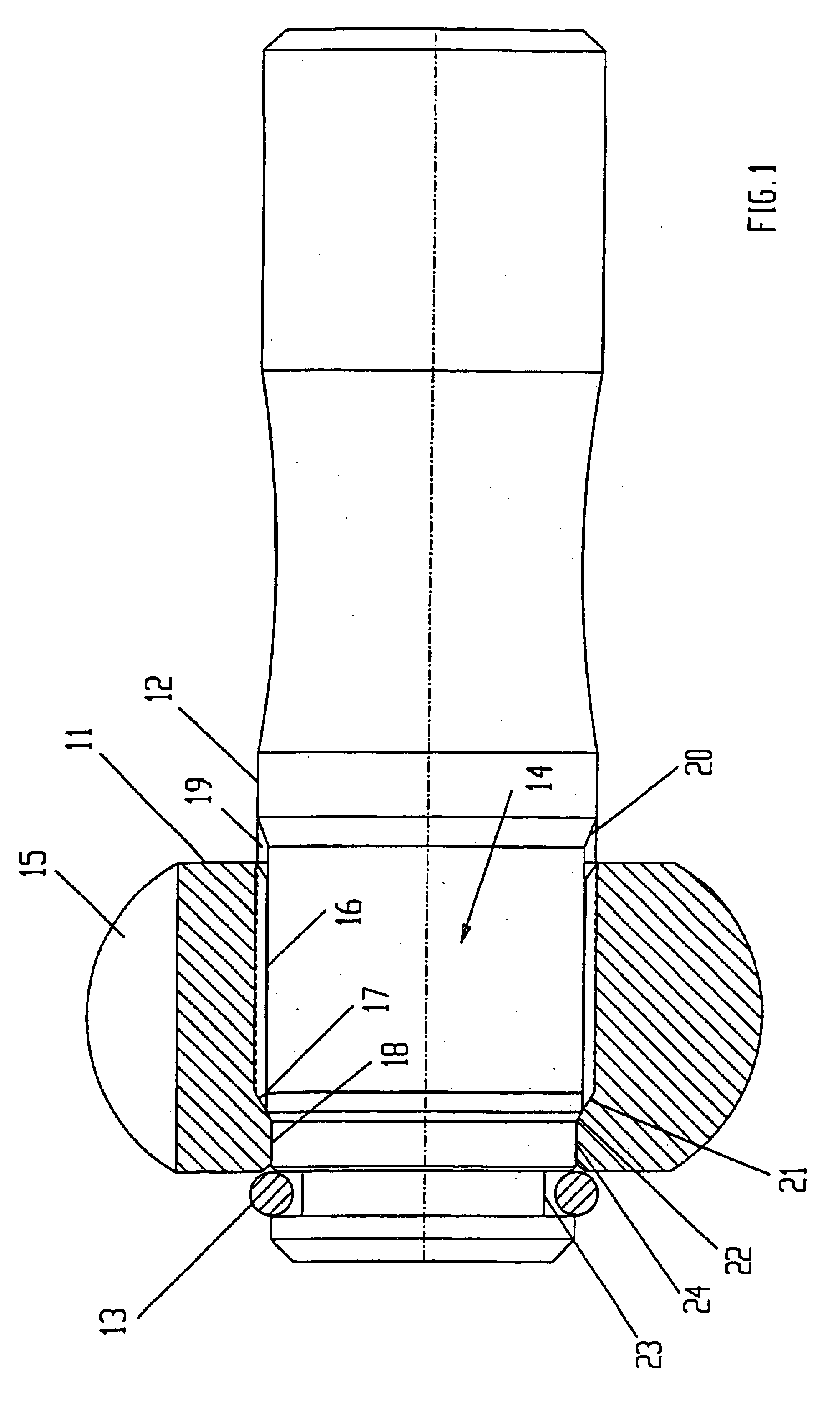
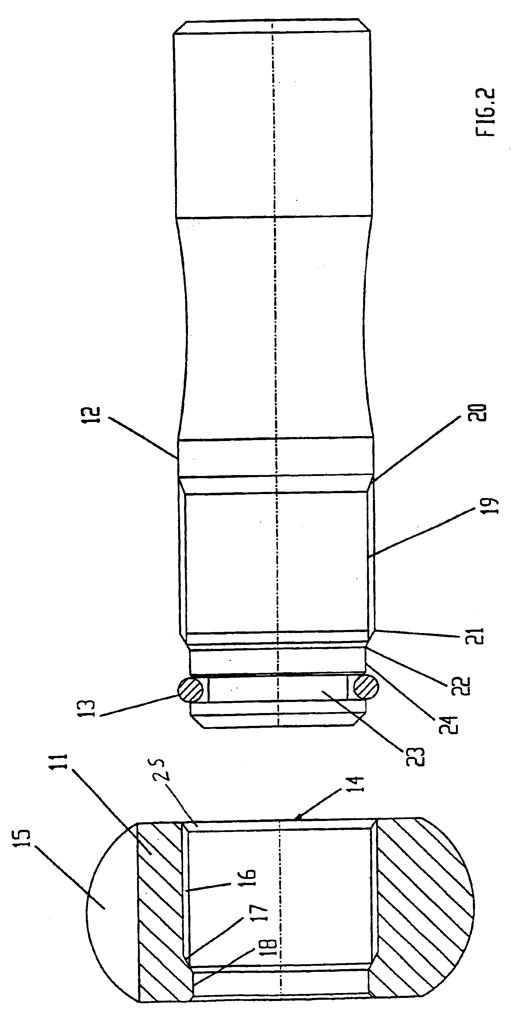
FIG. 1 shows an assembly including an inner joint part 11, a shaft journal 12 and a securing ring 13 in which the below-mentioned individual characteristics can be identified. The inner joint part 11 comprises a through-aperture 14 and ball grooves 15 for receiving torque transmitting balls. The through-aperture comprises a portion with an inner toothing 16, a run-out 17 of the shaft toothing as a well a smooth bore 18 with a reduced diameter. Into the hub member 11 there is inserted the shaft 12 whose shaft toothing 19 complements the inner toothing and whose toothing run-out 20 is positioned at a distance from the inner joint part. A stop cone 22 in front of the toothing start 21 is axially supported on the toothing run-out 17 of the inner toothing 16 of the inner joint part 11 to prevent the shaft journal 12 from being introduced further, which would be possible bearing in mind the toothing length. The stop cone is followed by a cylindrical portion 24 with a reduced diameter whic...


PUM

PropertyMeasurementUnit
velocityaaaaaaaaaa
lengthaaaaaaaaaa
axial lengthaaaaaaaaaa

Abstract

A production method involving forming an inner joint part of a constant velocity universal ball joint in the form of a hub member (11) which comprises a central through-aperture (14) with inner toothing (16) for receiving a shaft journal (12), and ball tracks (15) for receiving torque transmitting balls on the outer circumference, wherein a blank with largely finish-formed ball tracks is produced by non-chip-forming deformation; wherein, at the blank, outer surfaces and a smooth through-aperture (14) are finish-turned; and wherein, during simultaneous working stages, the ball tracks (15) are calibrated by non-chip-forming deformation and the inner toothing (16) in the through-aperture (14) is produced by pressing in a non-chip-forming way.

Description

TECHNICAL FIELDThe invention relates to a process of producing, by forming and machining, an inner joint part of a constant velocity universal ball joint in the form of a hub member which comprises a central through-aperture with inner toothing for receiving a shaft journal, and tracks for receiving torque transmitting balls on the outer circumference. The invention further relates to a process for producing a shaft journal for being inserted into the above-mentioned inner joint part. Furthermore, the invention is referred to a hub member and shaft journal assembly.BACKGROUND OF THE INVENTIONA connecting assembly between an inner joint part and an inserted driveshaft of the foregoing type is known from DE 42 40 131 C2. The inner toothing comprises a delimited axial length inside the through-aperture which continues on an untoothed portion. The end of the inner toothing serves as an axial stop for the shaft toothing of the inserted driveshaft. The inner toothing is produced in a blin...

Claims


Application Information

Patent Timeline
Patent Type & Authority Patents(United States)
IPC IPC(8): B21K1/76B21K1/00B23P11/00B23P15/00F16D3/16F16D3/223F16D3/20
CPCB21K1/762B23P11/00B23P15/00F16D3/223B23P2700/11Y10T403/7035F16D2003/22313F16D2250/00F16D2300/12Y10S464/906
Inventor FUHRMANN, PETERFRIELINGSDORF, HERBERTHAINZ, VOLKERSPOLMAYEUR, JEAN
Owner GKN AUTOMOTIVE GMBH
Why Eureka
Try Eureka