Shift range changeover mechanism

a technology of shifting range and shift range, which is applied in mechanical equipment, transportation and packaging, and machining, etc., can solve the problems of high accuracy and difficulty in detecting the precise rotational position of the range control shaft, and achieve the effect of eliminating the loosening of the spline connection

Inactive Publication Date: 2005-04-12
AISIN AW CO LTD
View PDF13 Cites 18 Cited by
  • Summary
  • Abstract
  • Description
  • Claims
  • Application Information

AI Technical Summary

Benefits of technology

Accordingly, it is an object of the present invention to eliminate spline connection looseness (play) between the range control shaft and the position detecting sensor (detecting mechanism), and to solve the problems

Problems solved by technology

However, the above-mentioned shift cable, which connects the shift lever and the manual valve, has many layout restrictions and the development of a range changeover mechanism that does not use such a shift cable is desired.
However, in the above-described range chang

Method used


Image

  • Shift range changeover mechanism
  • Shift range changeover mechanism
  • Shift range changeover mechanism

Examples


Embodiment Construction

Hereinafter, preferred embodiments of the present invention will be described in detail with reference to the accompanying drawings.

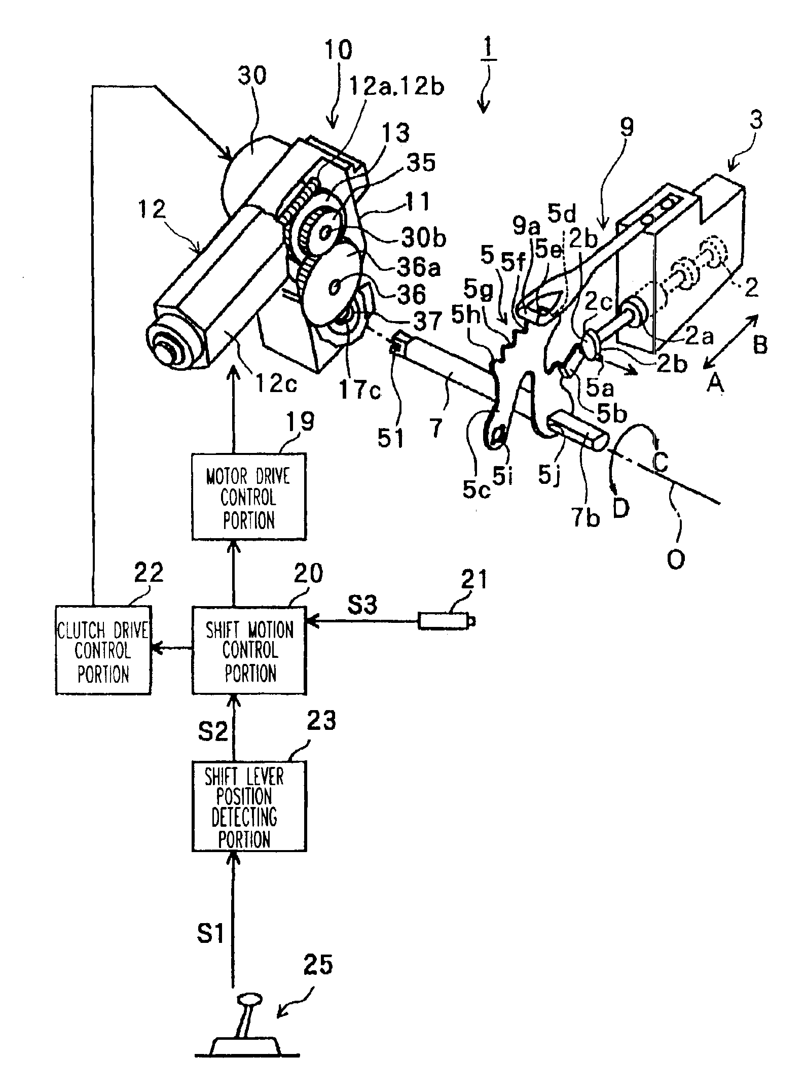
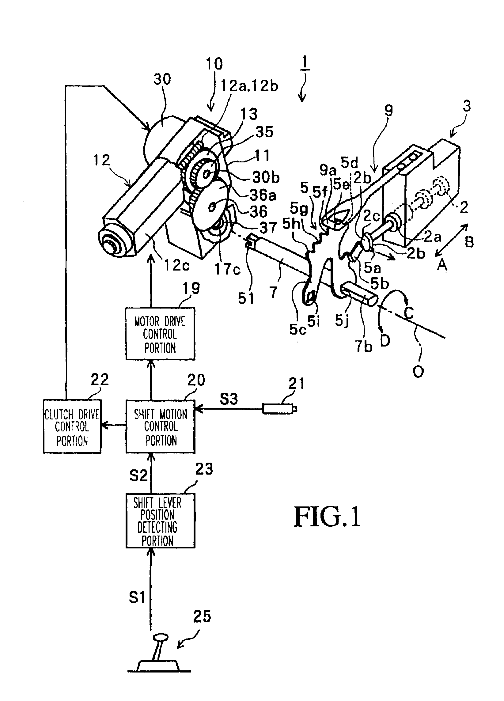
FIG. 1 shows one preferred embodiment of a vehicle range changeover (range shifting) mechanism 1 of the present invention as including a manual valve 2, which is a changeover valve that is a portion of an automatic transmission such as a multi-stage automatic transmission (not shown) or a continuously variable transmission (not shown). The manual valve 2, which serves as a “shift range operator,” is stored in a valve body 3 formed as a portion of a cover of the automatic transmission. The manual valve 2, as mounted within the valve body 3 is movable in the directions of Arrows A and B, i.e., directions of movement of spool 2a of the valve 2. The automatic transmission, by moving the manual valve 2 in the directions of Arrows A and B between predetermined positions, sequentially shifts from Arrow A towards Arrow B in the figure, for example, in the order...


PUM


Abstract

A vehicle range changeover mechanism is driven in response to operation of a shift lever. The range changeover mechanism has an output sector gear that is unrotatably connected to a range control shaft, and a position detecting sensor, a portion of which that is interlocked with and connected to the range control shaft. Looseness between the output sector gear and the position detecting sensor portion is eliminated by provision of a leaf or spring plate, thereby assuring rotation of the position detecting sensor portion corresponding one to one with the rotational motion of the range control shaft.

Description

INCORPORATION BY REFERENCEThe disclosure of Japanese Patent Application No. 2002-054717 filed on Feb. 28, 2002, including the specification, drawings and abstract, are incorporated herein by reference in its entirety.BACKGROUND OF THE INVENTION1. Field of the InventionThe present invention relates to a shift range changeover mechanism mounted in a vehicle or the like, more specifically, it relates to a range changeover mechanism with a drive such as an electric motor which operates in response to the operation of shift range selector such as a shift lever, and controls, for example, a hydraulic control device to change a shift range.2. Related ArtConventionally, a range changeover mechanism includes a manual valve that changes the shift range within a transmission and a shift lever provided in the interior of a vehicle and connected to the manual valve via a shift cable. Thus, in such a mechanism, the shift lever operates the manual valve via the shift cable with operation by a driv...

Claims


Application Information

Patent Timeline
IPC IPC(8): F16H59/08F16H61/28F16H61/32F16H59/10
CPCF16H59/08F16H61/32F16H59/105Y10T74/2003F16H2061/326Y10T74/19251
Inventor TSUZUKI, SHIGEOMAEDA, JIROOHKOSHI, NAOKI
Owner AISIN AW CO LTD
Why Eureka
Try Eureka