Interior rearview mirror assembly with polymeric components

a technology for rearview mirrors and components, applied in the field of rearview mirrors for vehicles, can solve the problems of difficult to maintain constant, consistent torque requirements for ball pivot joints, and inability to adjust, so as to improve performance and facilitate manufacturing

Inactive Publication Date: 2005-04-12
DONNELLY CORP
View PDF70 Cites 86 Cited by
  • Summary
  • Abstract
  • Description
  • Claims
  • Application Information

AI Technical Summary

Benefits of technology

The present invention provides an improved rearview mirror assembly for vehicles. In particular, this invention provides an interior rearview

Problems solved by technology

However, these rearview mirror support arms have been difficult to manufacture and have encountered numerous drawbacks in use.
For example, during high volume production of such supports, it is difficult to maintain the constant, consistent torque requirements for the ball pivot joints in order to properly support the rearview mirror assembly in its cantilevered position.
Once the outer tube of the conventional support arm is crimped over at its ends, it cannot be adjusted.
If the frictional resistance or torque required for pivotal movement is not correct, the assembly must be scrapped.
Moreover, each support arm requires a relatively large number of parts such that the arm is expensive to manufacture.
Once the assembly is properly painted, handling of the assembly during manufacture, shipping and/or installation can often damage the paint, again requiring the assembly to be discarded.
Further, since the internal spring of such assemblies causes the frictional resistance at the two ball joints to be interdependent on

Method used


Image

  • Interior rearview mirror assembly with polymeric components
  • Interior rearview mirror assembly with polymeric components
  • Interior rearview mirror assembly with polymeric components

Examples


embodiment 600

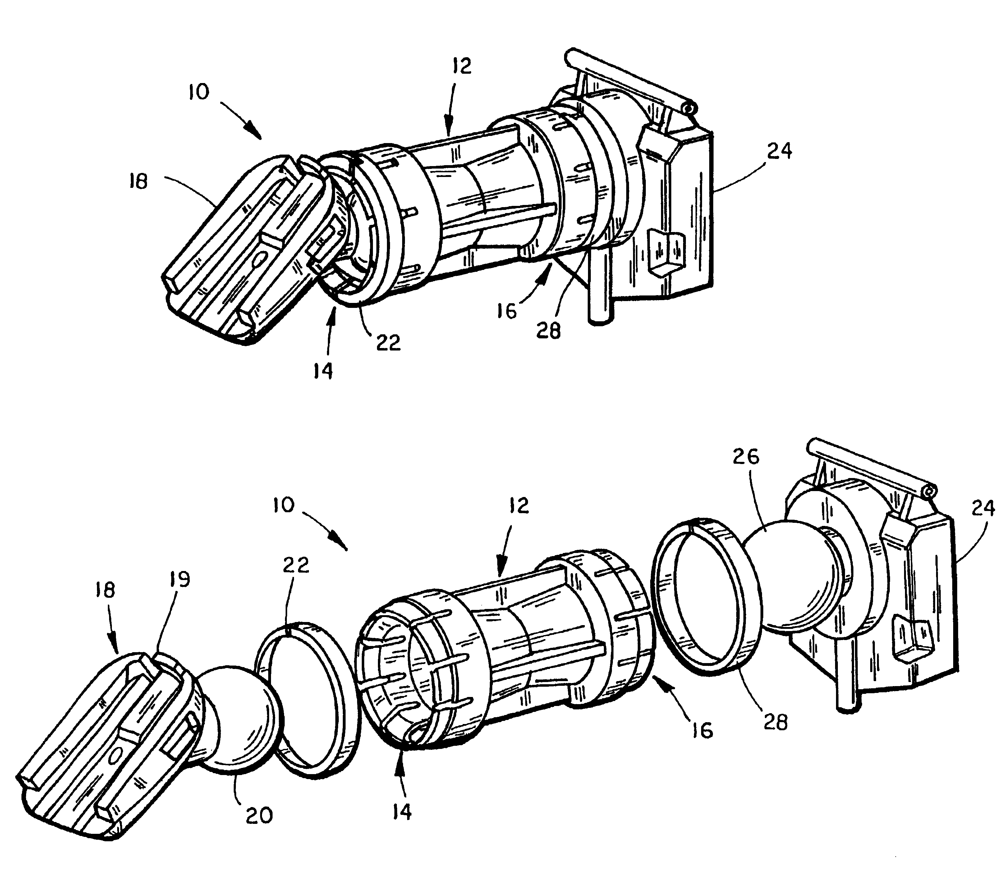
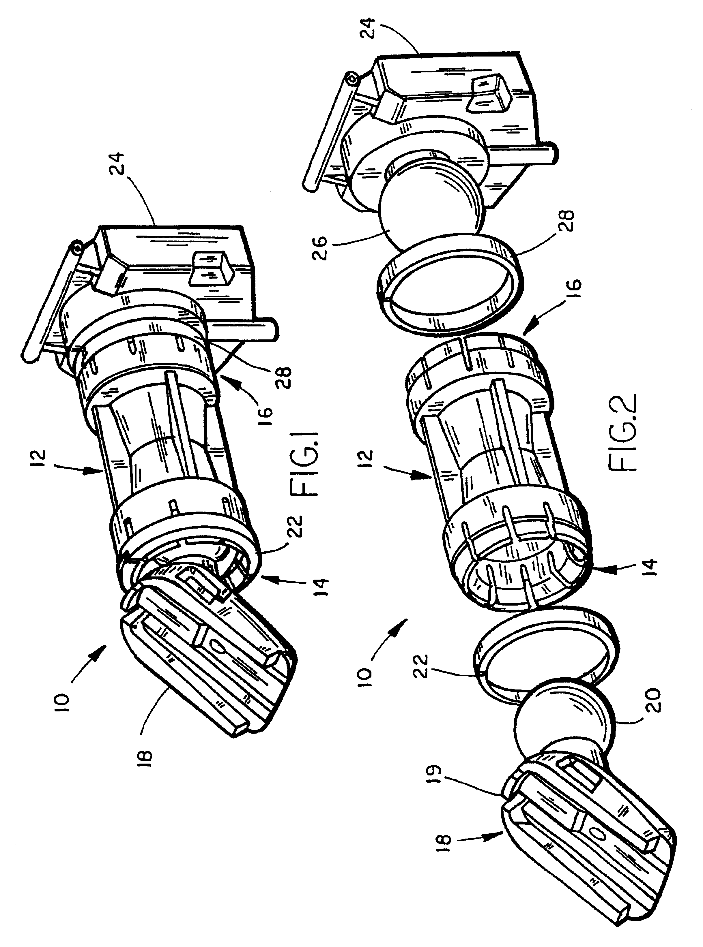
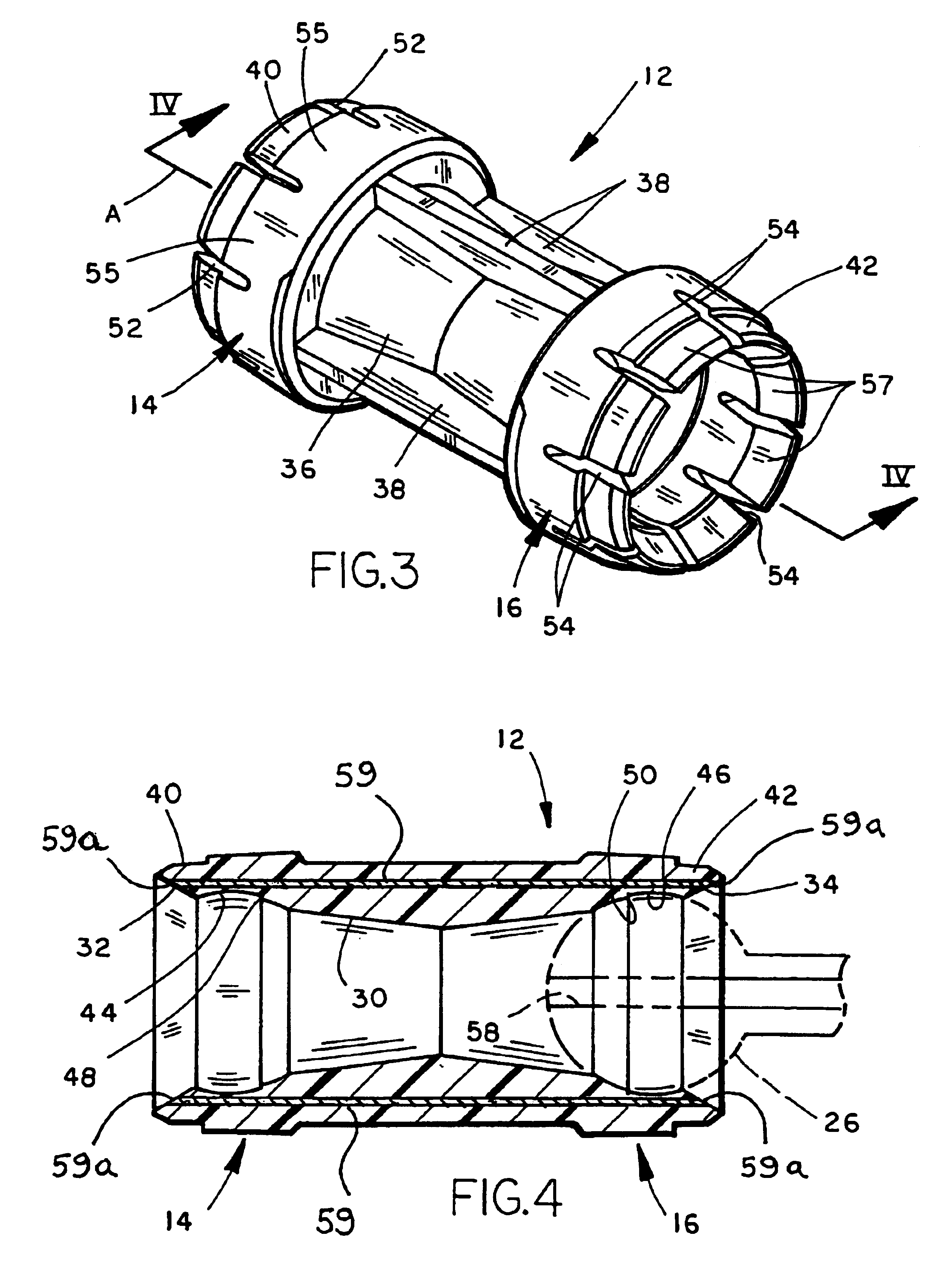
As shown in FIG. 46, a further embodiment 600 of the rearview mirror support (that is preferably formed of a polymeric resin such as by injection molding) of the present invention is shown including a modified continuous sleeve 602 including a socket 604 adjacent one end for receiving a ball pivot member preferably compression fitted therein for an interference fit within the socket as described above, and a socket 606 at the other end for similarly receiving a ball pivot member from a rearview mirror assembly component as shown in phantom. Preferably, as shown in FIG. 46, sockets 604, 606 each have a cross-sectional shape which is slightly different from that of a generally spherical ball pivot member. The diameter of sleeve 602 at left end 602a is larger than the diameter of end 602b such that that the wall thickness of the tube adjacent socket 604 is greater than the wall thickness adjacent socket 606. This provides a difference in torque or frictional resistance to pivotal movem...

embodiment 630

With reference to FIG. 50, a further embodiment 630 of the rearview mirror support of the present invention includes a molded plastic, rectilinear, cylindrical sleeve or tube 631 having a socket 632 at the windshield or channel mount end and a socket 634 at the mirror assembly end. Sockets 632, 634 are designed to receive ball pivot members therein with an interference fit and a desired frictional resistance to pivotal movement using one or more of the methods described above. In addition, sleeve 631 includes a vibration reducing or dampening element inserted or incorporated in the tube such as a cork, foam (such as polystyrene foam), thermoplastic elastomer, or urethane dampening plug or member 636 press-fitted within the inner diameter of the tube or adhered therein centrally between sockets 632, 634 with a suitable adhesive and / or mechanically. Alternately, dampening member 636 could be co-injected with sleeve 631 from the same or a different material rather than separately forme...

embodiment 670

With reference to FIGS. 58-61, yet another embodiment 670 of the rearview mirror or vehicle accessory support sleeve of the present invention is shown. Sleeve 670 is preferably molded from a polymeric material such as those described above, including polybutylene terepthalate (PBT), calcium carbonate polypropylene or polypropylene. Sleeve 670 is molded in one piece and includes a center section 672 having a cylindrical outer surface, a windshield or channel mount end 674 having a conical outer surface, and a tapered mirror assembly end 676 also having a conical outer surface having a taper which is larger than that for section 674. Conical, tapered end section 674 includes plurality of four axially extending slots 678 spaced equidistantly therearound, while conical end 676 includes four equidistantly spaced slots 680. Just as in other embodiments of the support sleeve, slots 678, 680 divide conical sections 674, 676 into segments or flanges which can individually flex and pivot to a...


PUM


Abstract

An interior rearview mirror assembly for vehicles incorporates a rearview mirror mount, a rearview mirror, and a rearview mirror support. The support is pivotally attached to the mirror mount by a first pivot element, and to the rearview mirror by a second pivot element. The mirror mount, support, a rearview mirror housing, and the pivot elements are each formed by molding from polymeric material having a respective color. In various embodiments, the colors may all be substantially the same, such as black, gray, tan, brown, burgundy, green, or another color, or may be different. In one form, the rearview mirror housing includes at least one electrical accessory. Electrical conductors may extend through the pivot elements and mirror support to the rearview mirror housing to provide an electrical connection for the electrical accessory to the vehicle electrical system. The pivot elements preferably include ball pivot members and sockets on various of the mirror mount, support and rearview mirror housing, and may include surfaces for enhanced frictional resistance to pivotal movement. In one form, the rearview mirror mount preferably includes receiving members which release the assembly from a windshield attachment member when sufficient force is applied such as upon impact.

Description

FIELD OF THE INVENTIONThis invention relates to rearview mirrors for vehicles and, more particularly, to interior vehicular rearview mirror assemblies providing improved support capacity, versatility, vibration performance, resistance to damage, and ease of manufacture.BACKGROUND OF THE INVENTIONInterior rearview mirror assemblies for vehicles are typically supported at the forward portion of the passenger compartment of the vehicle by a support or linkage which is most often secured either to the inside surface of the windshield or to a mounting assembly at the forward edge of the headliner on the interior vehicle roof. In either case, a mounting assembly includes a support arm connected to the rearview mirror assembly, the support arm typically including a pair of ball pivot joints allowing adjustment of the position of the rearview mirror assembly for proper vision by various vehicle drivers. A widely used, conventional support arm is that shown in U.S. Pat. No. 4,254,931 and inc...

Claims


Application Information

Patent Timeline
IPC IPC(8): B60R1/04B60R1/02F16C11/06F16M11/14F16M11/02
CPCB60R1/04F16C11/06F16M11/14F16M13/02F16M11/2078Y10T403/32311F16M2200/022
Inventor MARCH, PHILLIP A.WELLER, ANDREW D.SKIVER, TIMOTHY G.BRUMMEL, MARK R.LYNAM, NIALL R.
Owner DONNELLY CORP
Why Eureka
Try Eureka