Ellipsoid generator

a generator and ellipsoid technology, applied in the field of coils, to achieve the effect of easy adaptability, high output and low cos

Inactive Publication Date: 2005-04-12
HARMONIC DRIVE INC
View PDF18 Cites 52 Cited by
  • Summary
  • Abstract
  • Description
  • Claims
  • Application Information

AI Technical Summary

Benefits of technology

The present invention applies to the shape and placement of a coil or conductor, the shape and placement of a permanent magnet rotor, rotating and pivoting means for the rotor or stator of the invention, and means for accelerating the rotor or stator of motors and generators of the invention herein described. The invention provides a high out-put, low cost, modular and easily adaptable, efficient energy and motion conversion dynamo-electric device. As a generator or motor, the stator or rotor may be caused to rotate or reciprocate along an axis with or without an axial shaft. Physical connections can be made directly to a rotor magnet or shaft, or connection can be made by magnetic coupling to an ad

Problems solved by technology

Also, as weight issues may develop with larger

Method used


Image

  • Ellipsoid generator
  • Ellipsoid generator
  • Ellipsoid generator

Examples


Embodiment Construction

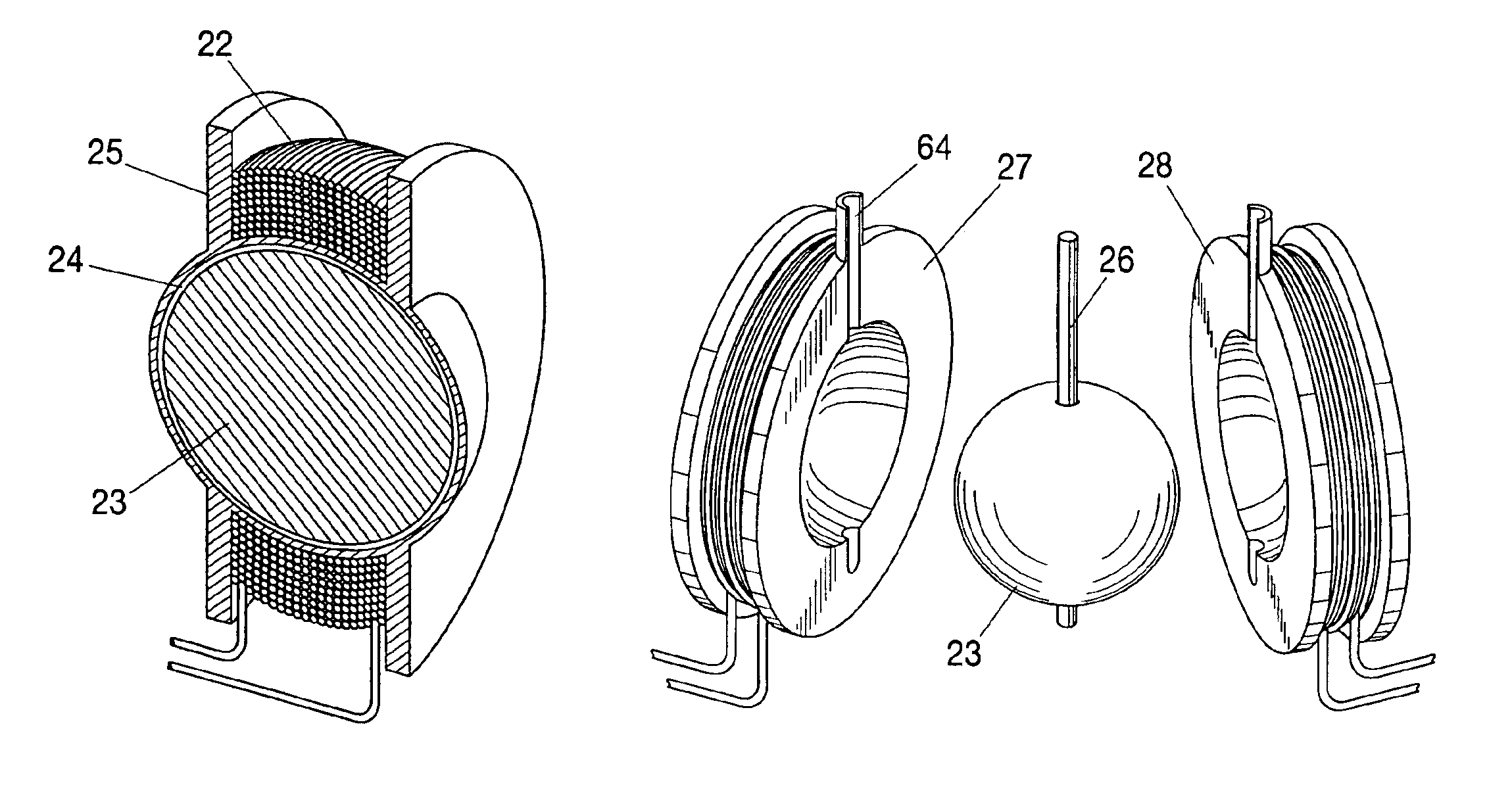
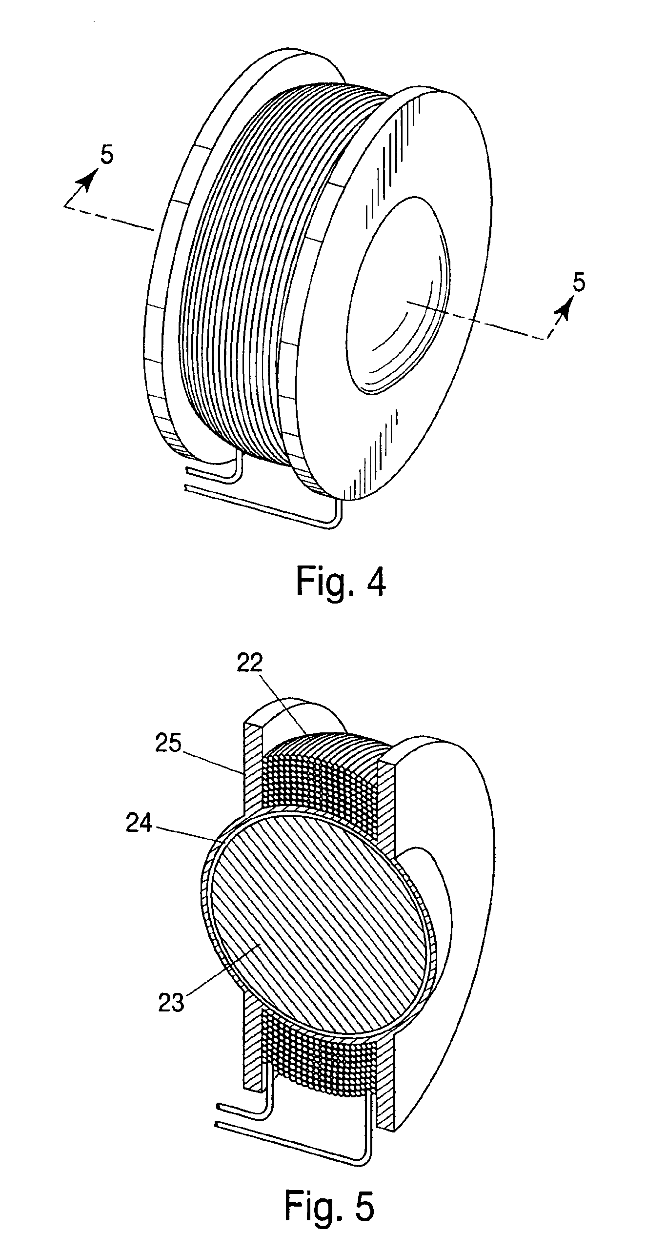
A dynamoelectric device is disclosed as generally illustrated in FIGS. 4-7 and FIGS. 9-15. In one embodiment, referring to FIGS. 4 and 5, a permanent magnet rotor 23 of ellipsoid shape has a N and S pole face equally divided along the surface area of the rotor. A stator coil 22 is axially centered and supported by bobbin-type structure 25 that provides an air gap dimension 24 about the rotor which can be filled by various methods with a ferrofluid (not shown) that provides means of rotor support for movement about an axis. A ferrofluid suspends the rotor magnet by attraction to the rotor surface area and provides a mostly uniform pressure gradient between the rotor and the inside wall cavity of the stator body 25.

In this example the rotor does not have a shaft. When used as a generator, means for accelerating the rotor in relation to the stator is provided by contact-less, magnetic coupling as disclosed with an additional element of either ferrous material (not shown) that is caused...


PUM


Abstract

A dynamoelectric device that is highly adaptable to a broad range of applications while providing robust output and energy conversion. The magnetic pole faces of the rotor lie in an ellipsoid. With or without a rotor shaft, the device allows options of either physical connection or contact-less, magnetic coupling. Surrounding the rotor is a brush-less stator having a bobbin-type, axial-centered coil conductor that provides a total capture of magnetic flux emanating from a rotor having an entire surface area of uniform flux density. Devices without a rotor shaft, and those having an air gap filled with ferrofluid, provide a two part generator with remarkable efficiency that is easily waterproofed and mechanically stable.

Description

STATEMENT REGARDING FEDERALLY SPONSORED RESEARCH OR DEVELOPMENTNot Applicable.BACKGROUND OF THE INVENTION1. Field of InventionThe invention pertains to coils, permanent magnet rotors, rotating and pivoting means for rotors of generators and motors, and means for accelerating the rotor or stator of these devices.A dynamo-electric device has a brush-less, substantially iron-less stator of bobbin-type coil structure axially centered and surrounding the rotor, closely approximating the contour of the ellipsoid or spherical, permanent magnet rotor. The rotor includes a permanent magnet having at least one north and south pole face as sectors of the ellipsoid shape having stable and substantially uniform flux density across the entire surface area of the rotor. Such devices need not include a shaft, having means for suspending, supporting, and accelerating the rotor, including magnetic coupling to various external devices. In some embodiments the rotor is allowed multiple degrees of freed...

Claims


Application Information

Patent Timeline
IPC IPC(8): H02K1/00H02K1/27H02K51/00H02K7/06H02K1/02H02K5/167
CPCH02K1/02H02K1/2726H02K51/00H02K7/06H02K5/1672
Inventor LONG, JOHNNY D.
Owner HARMONIC DRIVE INC
Why Eureka
Try Eureka