State surveillance system and method for an object and the adjacent space, and a surveillance system for freight containers

a surveillance system and surveillance system technology, applied in the direction of burglar alarm mechanical actuation, data switching network, instruments, etc., can solve the problems of difficult cutting hard metal to open the door, serious problems, and low security level

Inactive Publication Date: 2005-04-12
OMRON CORP MANAGEMENT CENT OF AMERICA INC +1
View PDF14 Cites 133 Cited by
  • Summary
  • Abstract
  • Description
  • Claims
  • Application Information

AI Technical Summary

Benefits of technology

1. In the conventional sensors to detect an abnormal status in a container, the installation positions of such sensors are fixed. This makes it easy for terrorists to pre-arrange an attack on the sensors. The nodes used in the inside-seals are not, installed at fixed positions in a container, because this irregular arrangement can prevent terrorists from pre-arranging an attack strategy. In order to avoid installing the nodes at fixed positions, they can be installed randomly or in irregular positions, which

Problems solved by technology

With this kind of mechanical seal, the material of the seal is made by hard metal and it is difficult to cut the hard metal to open the door.
It is, however, relatively easy to copy a key and this can lower the security level.
This will be a serious problem specially against terrorists bringing dangerous materials into the container.
This results in the increase of the number of containers to be checked.
Since this kind of container is installed outside of the freight container, however, it is relatively easy for unauthorized people to sleep the sealing before they attempt the unauthorized access into the container, such as by freezing the electronic circuit rapidly to sleep the monitoring function of the door.
It is not possible to fool the device and not possible to copy the identical device for fooling.
The transmitted data between the device and the recording unit is encrypted by 3 DES, and this makes it impossible to copy the data for illegal usage.
1) Since the location of sensors is fixed, if someone breaks a portion of the container wall, which the sensors cannot detect, this system does not work.
2) If the controller and sensors are illegally replaced when the system cannot communicate with the center wirelessly during the time that the door is open, and after the dangerous materials are loaded in, in other words, during the time that the system is changed to the inoperative mode to keep recording, then it is no longer possible to detect the fact that the door is illegally opened or closed.
This results in the loading of dangerous materials into the container.
As previously mentioned, the weakness of the system is caused by the fact that the security system is apparent visually before the illegal operation is attempted.
2) Another problem of this system is that, if the controller and sensors are illegally replaced when the system cannot communicate with the center wirelessly during the time that the door is open, and after the dangerous materials are loaded in, the system is unable to re

Method used


Image

  • State surveillance system and method for an object and the adjacent space, and a surveillance system for freight containers
  • State surveillance system and method for an object and the adjacent space, and a surveillance system for freight containers
  • State surveillance system and method for an object and the adjacent space, and a surveillance system for freight containers

Examples


second embodiment

According to the first preferred embodiment of this invention, the link information mentioned above can be expressed by whether a communication between the two nodes is established directly, or if it requires to be relayed by other nodes. the link information can be expressed by the distance between the node, which is measured by UWB electric wave.

One way to detect the node distribution information is disclosed in U.S. Pat. No. 6,028,857, which discloses a communication network provided with a self-organizing network, which is applied in the first preferred embodiment of the present invention. This self-organizing network is a kind of a relay system to communicate between a plurality of nodes, each of which can communicate only with their neighboring nodes by low-power electric waves. Each node is provided with relaying counts to all of other nodes according to the self-organizing network. The relaying count is defined by how many relays are needed to send a message to the other no...

first preferred embodiment

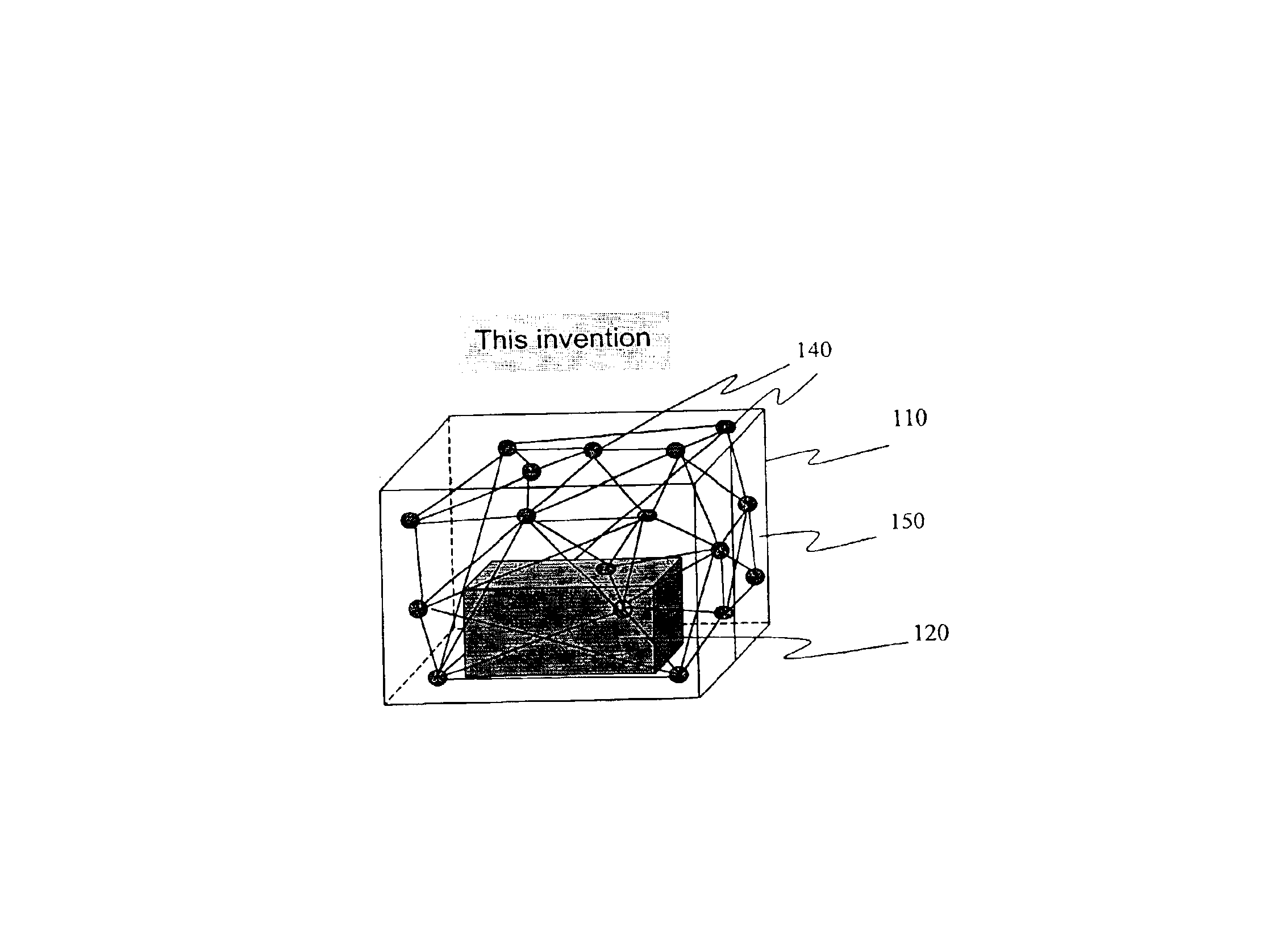
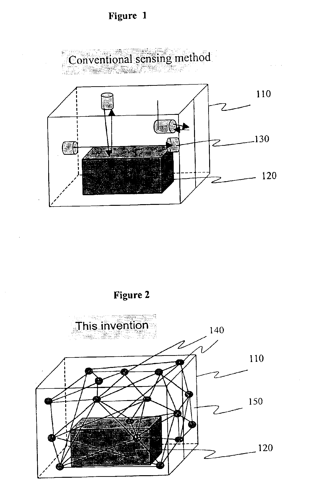
According to the first preferred embodiment, a plurality of nodes (communication nodes) are configured so that they can communicate with each other by low-power electric waves in the self-organizing communication network. With this configuration, it is possible not only to save battery power, but also to express the spatial status of the communication nodes in a container by the communication links between the nodes. In the system configured above, each node is able to communicate directly only with their neighboring nodes. The self-organizing communication network is disclosed in U.S. Pat. No. 6,028,857.

The following is a description of the communication nodes that are installed in a container to be monitored. A plurality of nodes are randomly installed on the inner walls or door of a container to be monitored. If a consigner can install the node, the consigner can install the node in the cargo loaded within the container. If the container is empty, or a consigner cannot install th...

second preferred embodiment

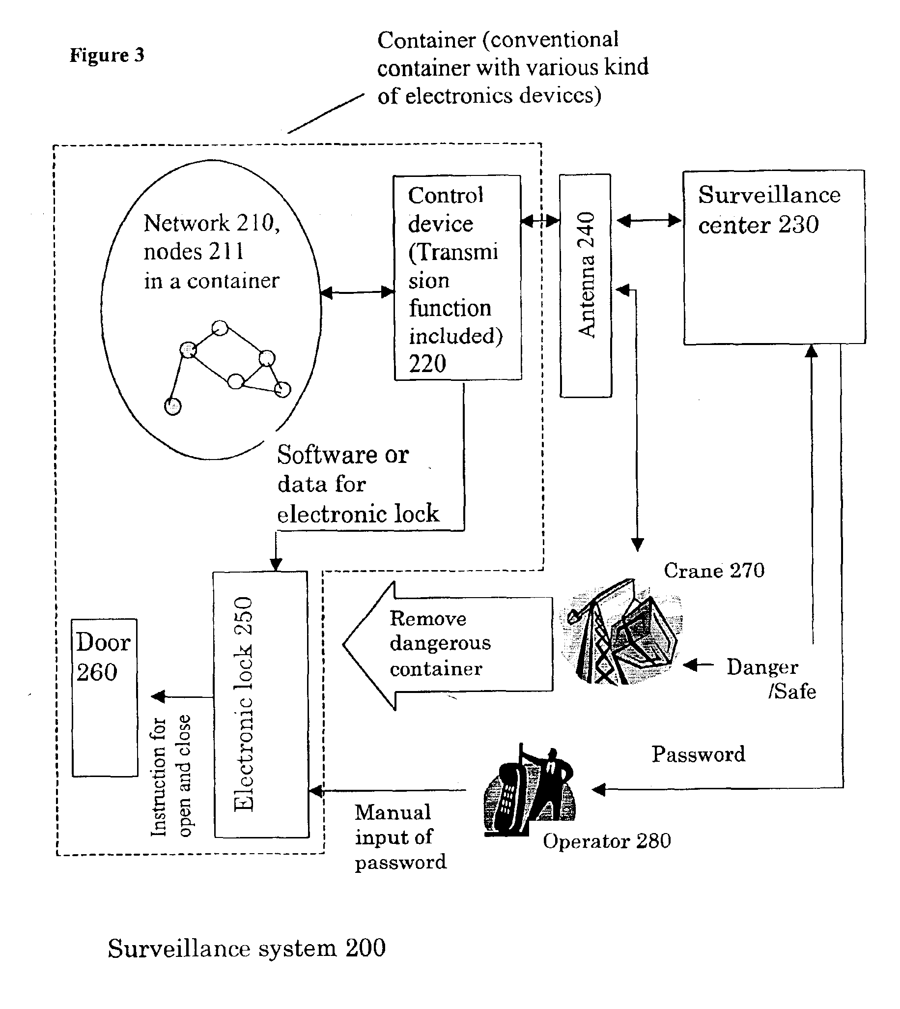
The process flowchart of the second preferred embodiment of this invention is shown in the flowchart of FIG. 13. The flowchart of FIG. 13 is related to the step of ST2309 shown in FIG. 23. FIGS. 22, 23, and 24 are flowcharts showing the processes performed in the surveillance system 200 according to this invention. This second preferred embodiment is characterized by the configuration which is robust to the various communicational situation, such as when a communication is disturbed due to an interruption by an article, a nodal function is stopped, a node has fallen down, or a direct wave is interrupted and indirect wave is transmitted. This characteristic feature is realized by the configuration, which makes it possible to measure the distance between the nodes in the communication network.

According to the second preferred embodiment, the network structure information of communication network 210 shown in FIG. 7 can be obtained by the direct communication between the nodes by UWB e...


PUM


Abstract

The objective of the present invention is to detect, using a universal method, any “movement” inside of the object being monitored, while maintaining the security of a container. The movement inside of the object to be monitored includes 1) a human movement when a human enters into a container to be monitored, 2) a movement to bring a foreign article in, 3) a movement to take cargo out. To achieve the objective, this invention uses the concept of a so-called “inside-seal”. In actual configuration, a plurality of communication units (communication nodes) are installed on the walls of the container. These communication units have a predetermined powered communication capability and form a communication network communicating with each other. A communication status between each node and all of the other nodes provided in the network, and a network graph matrix is generated which defines the nodal relationship between the nodes. Since the matrix is determined not only by the property of the object to be monitored, but also by the spatial condition within the container, it is possible to detect even a small change in the space. According to the first preferred embodiment, each node transmits a low power electric wave which can reach only neighboring nodes, and each node can transmit data to remote nodes only by relaying the data to the neighboring nodes. The relaying counts (HOP counts) of each node to communicate with all of the other nodes are obtained, and based on these relaying counts, a network graph matrix is generated which defines the relaying counts to communicate between all nodes. According to the second preferred embodiment, each node transmits UWB waves to all of the other nodes, which can reach to all of the other nodes, and the distances between all the nodes are measured and a network graph matrix between all the nodes is generated.

Description

FIELD OF TECHNOLOGY OF THE INVENTIONThe present invention relates to a Surveillance system to monitor any movement of an object of surveillance and the space proximate to the object (e.g. inside of warehouse, containers, vehicles, office or dwelling rooms, or the outside area of the warehouse), and a surveillance method using the same. This invention further relates to a detecting system to detect any unauthorized access into a freight container and swapping of the authorized freight container with an unauthorized freight container.This is a continuation-in-part application of currently pending U.S. patent application filed Feb. 25, 2002, (application Ser. No.: 10 / 080,927), U.S. patent application filed Apr. 10, 2002, (application Ser. No.: 10 / 119,310).BACKGROUND OF THE INVENTIONAs exemplified by the terrorist attacks in the United States on Sep. 11, 2001, the increasingly frequent acts of terror internationally dictate the importance of risk management for freight containers that a...

Claims


Application Information

Patent Timeline
IPC IPC(8): G08B25/00G08B13/181G08B13/18G08B13/24
CPCG08B13/181G08B13/24G08B25/009G08B13/2491G08B13/2462
Inventor HISANO, ATSUSHINAKAMURA, AKIHIKO
Owner OMRON CORP MANAGEMENT CENT OF AMERICA INC
Why Eureka
Try Eureka