Monitoring system with thermal probe for detection of layers in stratified media

a stratified media and monitoring system technology, applied in the direction of fluid pressure measurement by mechanical elements, electric/magnetic measuring arrangements, dispersed particle filtration, etc., can solve the problems of system failure, ground and surface water can become polluted, and system failures and other problems

Inactive Publication Date: 2005-04-12
CIDRA CORP SERVICES
View PDF21 Cites 17 Cited by
  • Summary
  • Abstract
  • Description
  • Claims
  • Application Information

AI Technical Summary

Benefits of technology

Advantageously, the present invention has as its primary object the provision of a system and method for monitoring the condition of stratified layers in a

Problems solved by technology

When the system is not operating properly and solids are suspended in the gray water, the drainage field can become clogged by solids such that the gray water ceases to be absorbed and dispersed properly thereby resulting in drainage field failure.
With this, ground and surface water can become polluted, and the system can otherwise malfunction.
Some of the sediment, however, will not be biodegradable and will remain at the bottom of the tank.
Notably, as the volumes of solids increase in the septic tank, the effectiveness of the biological decomposition tends to increase thereby leading to a decreased rate of accumulation even with a constant input rate.
A major difficulty in septic tank operation is that, because it is necessarily carried out underground, the status of the septic tank is generally difficult or impossible to perceive.
With this, the first indication of a failure in the system often comes in the form of the unpleasant backup of w

Method used


Image

  • Monitoring system with thermal probe for detection of layers in stratified media
  • Monitoring system with thermal probe for detection of layers in stratified media
  • Monitoring system with thermal probe for detection of layers in stratified media

Examples


case 1a

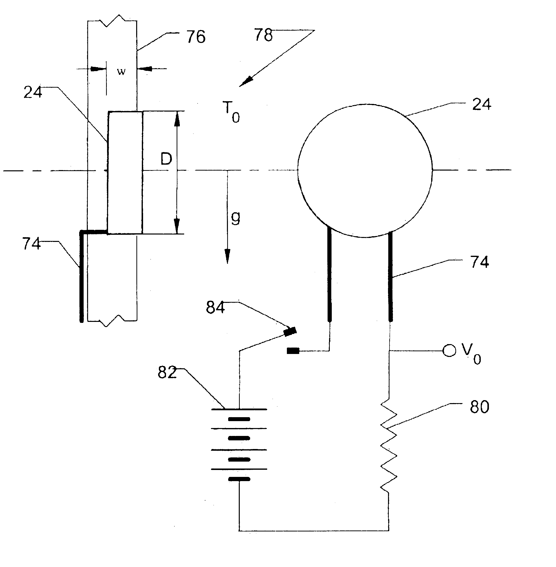
ference to the ring electrode coordinate system depicted in FIG. 5 and to the hemispherical and ring electrode depictions of FIGS. 6A, and 6B, consider first a hemispherical electrode sensor 24 or 25 of radius, r, on the surface of a non-conducting cylinder, such as the elongate tube 15, of radius, b, in a fluid 110 with electrical conductivity, σ. If I is the current from the electrode sensor 24 or 25 to the fluid 110 and r<<b, the potential of the electrode sensor 24 or 25 will be given by

V(r)=(I / 2πσ)1 / r

where we have set the potential of the fluid 110 at infinity equal to zero.

Case 1b. Consider a ring electrode sensor 24 or 25 of radius, r, on the surface of a non-conducting cylinder, such as the elongate tube 15, of radius, b, in a fluid 110 with electrical conductivity, σ, as shown in FIG. 5. If I is the current from the electrode sensor 24 or 25 to the fluid 110 and r<<b, the potential of the electrode sensor 24 or 25 will be given by

V(r,b)=(I / 2πσ)F(b,r)

wher...

case 3a

hemispherical electrode sensor 24 or 25 of Case 1a is located at a height, a, above a horizontal boundary 111 at z=0 between two fluids with different conductivities and the axis of the cylinder, such as the elongate tube 15, is vertical as shown in FIG. 6a, then the potential of the electrode 24 or 25 obtained by the method of images is V⁡(r,a)=(I2⁢ ⁢π⁢ ⁢(σ1+σ2))⁢((1+σ1σ2)⁢1r+(1-σ1σ2)⁢12⁢ ⁢a):a>r V(r)=I / π(σ1+σ2): a=0V⁡(r,a)=(I2⁢ ⁢π⁢ ⁢(σ1+σ2))⁢((1+σ2σ1)⁢1r-(1-σ2σ1)⁢12⁢ ⁢a):a<-r

where σ1 and σ2 are the conductivities of the lower and upper fluids respectively.

case 3b

ring electrode 24 or 25 of Case 1b is located at a height, a, above a horizontal boundary 111 at z=0 between two fluids with different conductivities and the axis of the cylinder, such as the elongate tube 15, is vertical as shown in FIG. 6b, then the electrode potential obtained by the method of images is V⁡(r,b,a)=(I2⁢ ⁢π⁢ ⁢(σ1+σ2))⁢((1+σ1σ2)⁢F⁡(r,b)+(1-σ1σ2)⁢F⁡(2⁢a,b)):a>rV⁡(r,b,0)=(Iπ⁡(σ1+σ2))⁢F⁡(r,b):a=0V⁡(r,b,a)=(I2⁢ ⁢π⁢ ⁢(σ1+σ2))⁢((1+σ2σ1)⁢F⁡(r,b)-(1-σ2σ1)⁢F⁡(2⁢a,b)):a<-r

4. Interface Resolution Functions

The relative potential of a hemispherical electrode 24 or 25 in a stratified fluid conductor (Case 3a) is shown as a function of a / 2r in FIG. 7a for various values of the conductivity ratio σ1 / σ2. It can be seen that the spatial resolution for such an electrode 24 or 25 is approximately the electrode diameter, 2r. The corresponding relative potential for a ring electrode 24 or 25 (Case 3b) is shown in FIG. 7b. In this case, the spatial resolution is approximately the cyl...


PUM

PropertyMeasurementUnit
Temperatureaaaaaaaaaa
Lengthaaaaaaaaaa
Electric potential / voltageaaaaaaaaaa

Abstract

A monitoring system such as a septic tank monitoring system for distinguishing between and identifying the location of a sedimentary layer, a scum layer, and any intervening liquid zone in a septic tank with an elongate sensing probe for being disposed in the septic tank, a plurality of sensors disposed along the sensing probe, and a remote monitor operably associated with the plurality of sensors, such as thermistors, for providing a remote indication to a septic tank operator of the location of the sedimentary layer, the scum layer, and any intervening liquid zone in the septic tank based on the signals from the plurality of sensors so that a septic tank operator can monitor the contents and condition of the septic tank without a need for excavating and physically inspecting the septic tank.

Description

FIELD OF THE INVENTIONThe present invention relates generally to measuring and testing methods and instruments. Stated more particularly, this patent discloses and protects a system and method for monitoring conditions within a container, such as the thickness and position of layers in stratified media, by use of an array of temperature transducers to detect differences in thermal and material properties.BACKGROUND OF THE INVENTIONAs one knowledgeable in the art will be well aware, a typical septic system is founded on a tank in which wastes are collected, settled, and partially digested. The septic tank leeches what is termed gray water into a drain field where it is dispersed. When the system is operating properly, the dispersed gray water will be substantially devoid of solid matter. When the system is not operating properly and solids are suspended in the gray water, the drainage field can become clogged by solids such that the gray water ceases to be absorbed and dispersed prop...

Claims


Application Information

Patent Timeline
IPC IPC(8): G01F23/24G01F23/00C02F1/00G01F23/22
CPCG01F23/00G01F23/246G01F23/242G01F23/22C02F1/008
Inventor KECK, JAMES C.
Owner CIDRA CORP SERVICES
Why Eureka
Try Eureka