Diagnostic apparatus and methods for a chemical detection system

a chemical detection and diagnostic equipment technology, applied in the direction of instruments, nuclear elements, material electrochemical variables, etc., can solve the problems of accelerating deterioration of the valve stem packing set, vocs that are typically handled by industrial plants, and vocs that are typically unusable in the atmosphere, so as to prevent chemical sensor damage

Inactive Publication Date: 2005-04-12
FISHER CONTROLS INT LLC
View PDF26 Cites 9 Cited by
  • Summary
  • Abstract
  • Description
  • Claims
  • Application Information

AI Technical Summary

Benefits of technology

In yet another aspect, the present invention teaches a method to detect excessive fugitive emission presence to prevent chemical sensor damage.

Problems solved by technology

Industrial plants that handle volatile organic compounds (VOCs) typically experience unwanted emissions of those compounds into the atmosphere from point sources such as smokestacks and non-point sources such as valves, pumps, and vessels containing the VOCs.
Fugitive emissions from control valves typically occur as leakage through the packing set around the valve stem.
Control valves used in demanding service conditions involving large temperature fluctuations and frequent movements of the valve stem commonly suffer accelerated deterioration of the valve stem packing set.
Thus, achieving a low percentage of leaking valves reduces the number of surveys required per year, which may result in large cost savings.
Numerous fault conditions may result in erroneous readings.
For example, variations in flow can change the thermodynamics of chemical sensing and induce errors.
Permanent shifts in sensor baseline frequency can result from undesired chemical exposures, particulate accumulation, and temperature and humidity extremes.
Furthermore, certain species of chemical sensors will suffer irreversible change when exposure levels exceed their saturation limit.
These fault conditions can produce measurement errors or “false positive” leak reports.
Responding to false positive leak reports could be as costly as performing the manual surveys.
This method is disadvantageous due to the required storage and maintenance of surrogate compounds within the measurement system.

Method used


Image

  • Diagnostic apparatus and methods for a chemical detection system
  • Diagnostic apparatus and methods for a chemical detection system
  • Diagnostic apparatus and methods for a chemical detection system

Examples


Embodiment Construction

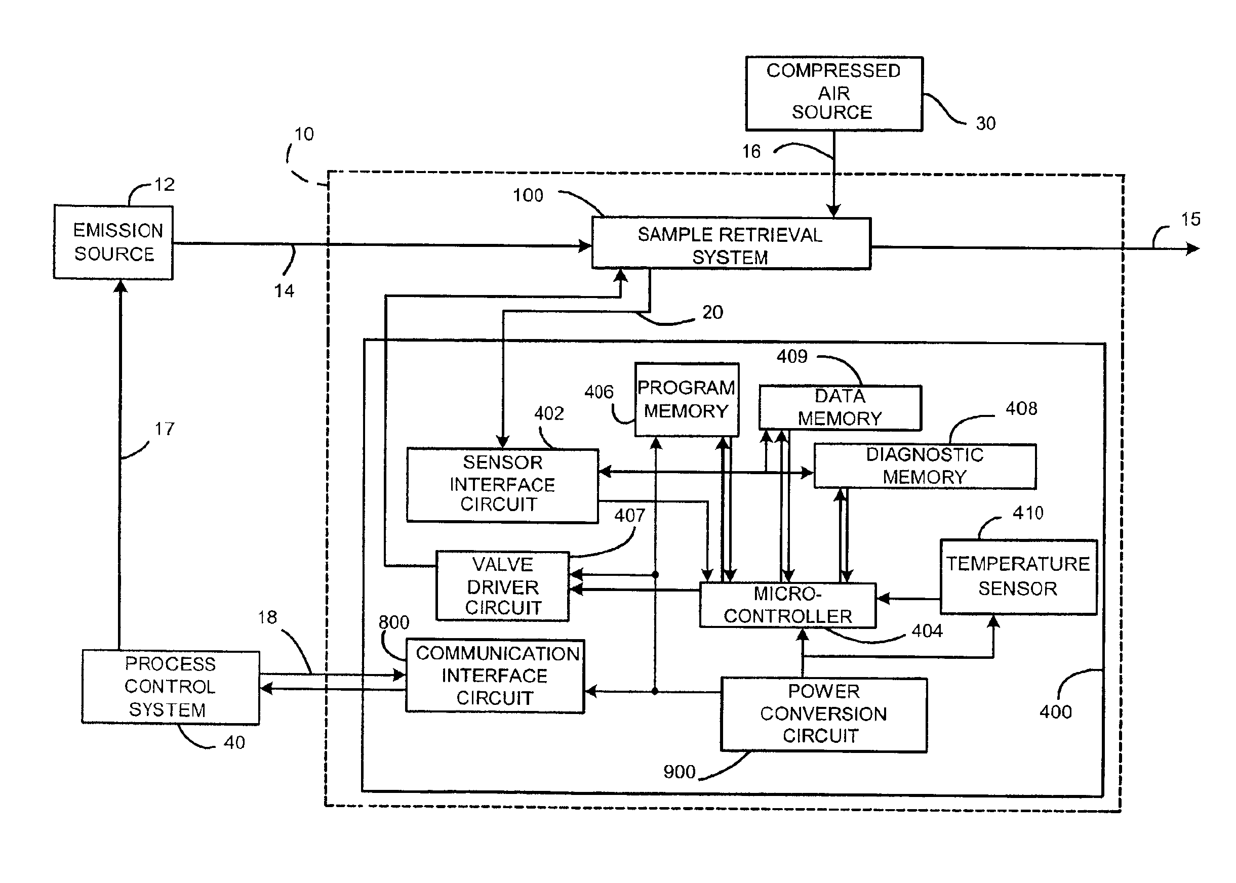
For any chemical detection system to perform adequately, numerous design techniques must be utilized. For example, a system designed to present the chemical sensors with the chemical species of interest must be fully functional prior to initiating a measurement scenario. Additionally, the chemical sensors must be designed to withstand contaminating elements within the operational environment. The present invention not only teaches those skilled in the art how to validate system operation, but also how to confirm the health and integrity of the chemical sensors themselves.

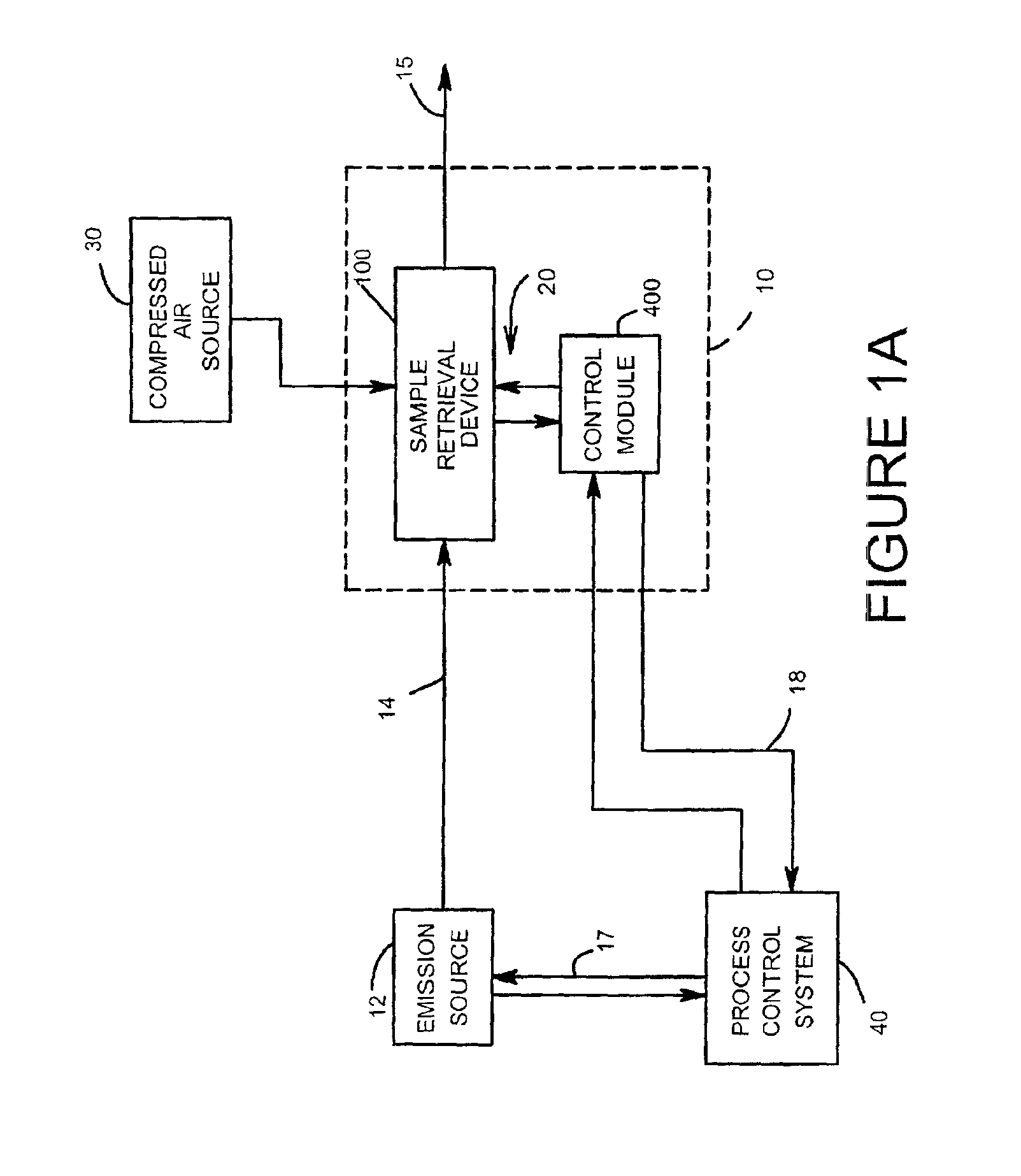
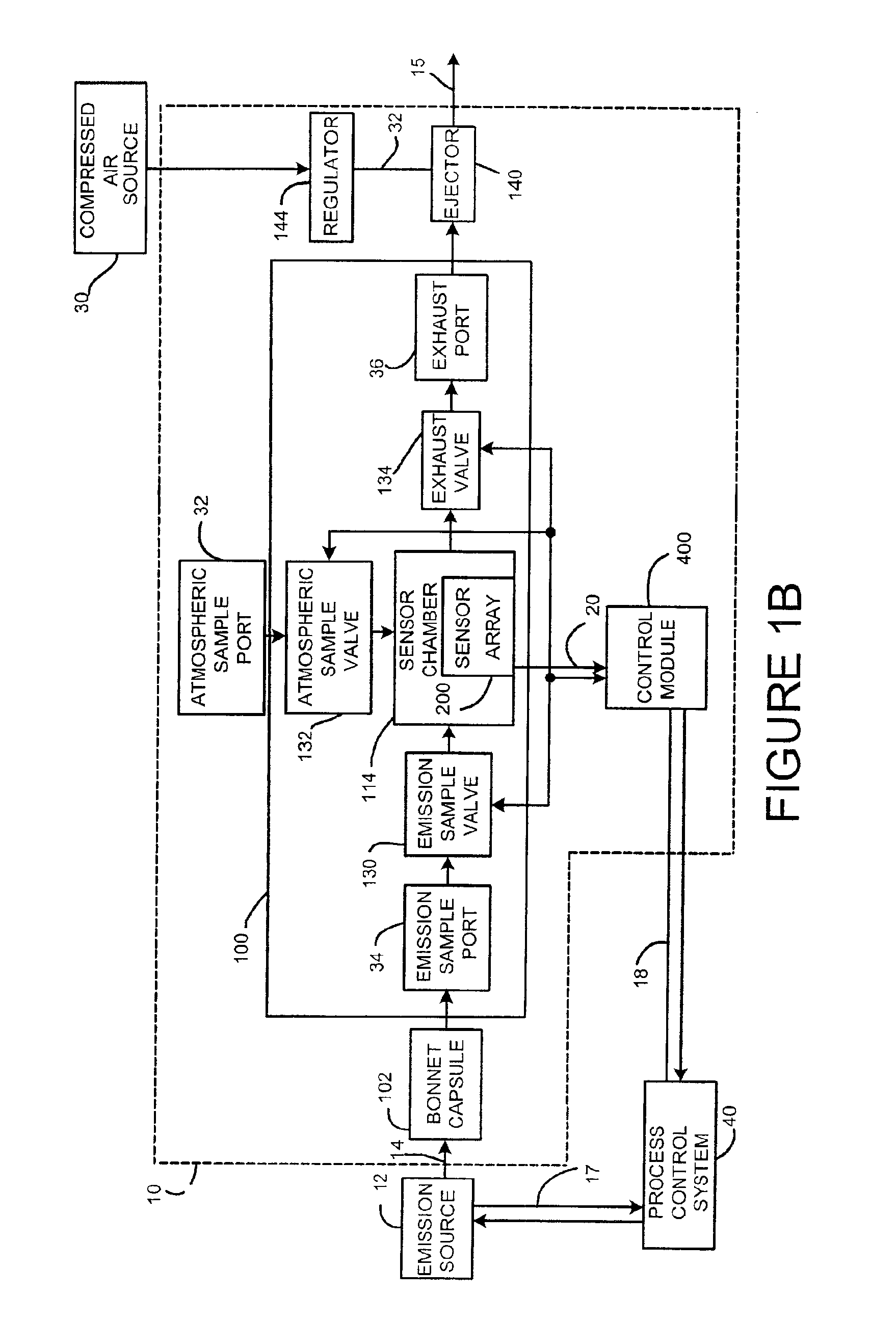
To fully appreciate the advantages of the present invention, it is necessary to have an understanding of the systems' components and how they operate to detect chemicals. Although the preferred embodiment teaches diagnostic techniques related to control valves, those skilled in the art will recognize the applicability to other process equipment such as pumps. Turning to the drawings and referring initially to FIG. 1...


PUM

PropertyMeasurementUnit
temperatureaaaaaaaaaa
resonant frequencyaaaaaaaaaa
frequencyaaaaaaaaaa

Abstract

A chemical detection system performs controlled exposures to diagnose the pneumatic components and chemical sensors prior to measuring a chemical emission. A control module provides the system control and data processing to perform the diagnosis. The control module manipulates an emission sample retrieval system to provide precise exposure during the diagnostic routines. A sensor interface circuit interrogates the chemical sensors and stores the data for analysis. The chemical sensor exhibits predictable changes in response during predetermined exposure scenarios. By utilizing numerous time domain signal processing techniques, both system and sensor level fault conditions are determined.

Description

FIELD OF THE INVENTIONThis invention relates to an apparatus and method for diagnosing a chemical detection system used for quantifying volatile organic emissions from equipment used in the process industry.BACKGROUNDIndustrial plants that handle volatile organic compounds (VOCs) typically experience unwanted emissions of those compounds into the atmosphere from point sources such as smokestacks and non-point sources such as valves, pumps, and vessels containing the VOCs. Emissions from non-point sources typically occur due to leakage of the VOCs from joints and seals and are referred to as “fugitive emissions”. Fugitive emissions from control valves typically occur as leakage through the packing set around the valve stem. Control valves used in demanding service conditions involving large temperature fluctuations and frequent movements of the valve stem commonly suffer accelerated deterioration of the valve stem packing set.The United States Environmental Protection Agency (EPA) ha...

Claims


Application Information

Patent Timeline
Patent Type & Authority Patents(United States)
IPC IPC(8): G01N33/00G01N35/00G01N5/02
CPCG01N33/007
Inventor DILGER, JOHN P.
Owner FISHER CONTROLS INT LLC
Why Eureka
Try Eureka