Molded plastic blade holder

a blade holder and molded plastic technology, applied in the field of molded plastic blade holders, can solve the problems of large vibration and noise emitted by rotary knives, damage to eardrums, and impair hearing, and achieve the effects of reducing noise and vibration, long life, and reducing noise emission

Inactive Publication Date: 2005-04-19
LONG JOHN W
View PDF5 Cites 19 Cited by
  • Summary
  • Abstract
  • Description
  • Claims
  • Application Information

AI Technical Summary

Benefits of technology

[0013]The present invention is directed to a combination of elements, specifically including a toroidal rotary knife blade having a sharpened circular lower edge and an upper blade holder engagement section and a blade holder for the toroidal rotary knife blade. The blade holder includes a generally toroidal blade holding ring having an upper gear-engaging section including a plurality of gear teeth formed thereon for intermeshing with a drive gear and a lower blade engagement and retention section adapted to receive and retain the toroidal rotary knife blade therein. The blade holding ring is constructed of material selected from the group consisting of plastic, polyvinyl chloride, polyethylene, polypropylene, polystyrene, vinyl, and polyethylene terephthalate. Finally, the generally toroidal blade holding ring is operative to reduce noise and vibration emitted therefrom during rotation of the generally toroidal blade holding ring by a drive gear due to the use of plastic const

Problems solved by technology

It has been found that these types of blades are very efficient at removing tissue from the carcass, but there are inherent problems with the use of these knives that have not been solved by the prior art.
One of these problems in the meat packing industry is the large amount of vibration and noise emitted by the rotary knives.
As a result, the metal-on-metal contact of the knife components operating at high-speeds would cause a high-pitched noise that could damage the eardrum and impair hearing.
Additionally, the lack of a damper in the drive mechanism and high-speed operation causes severe vibration of the knife that could re

Method used


Image

  • Molded plastic blade holder
  • Molded plastic blade holder
  • Molded plastic blade holder

Examples


Embodiment Construction

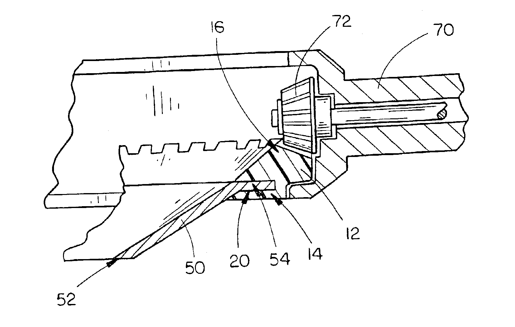
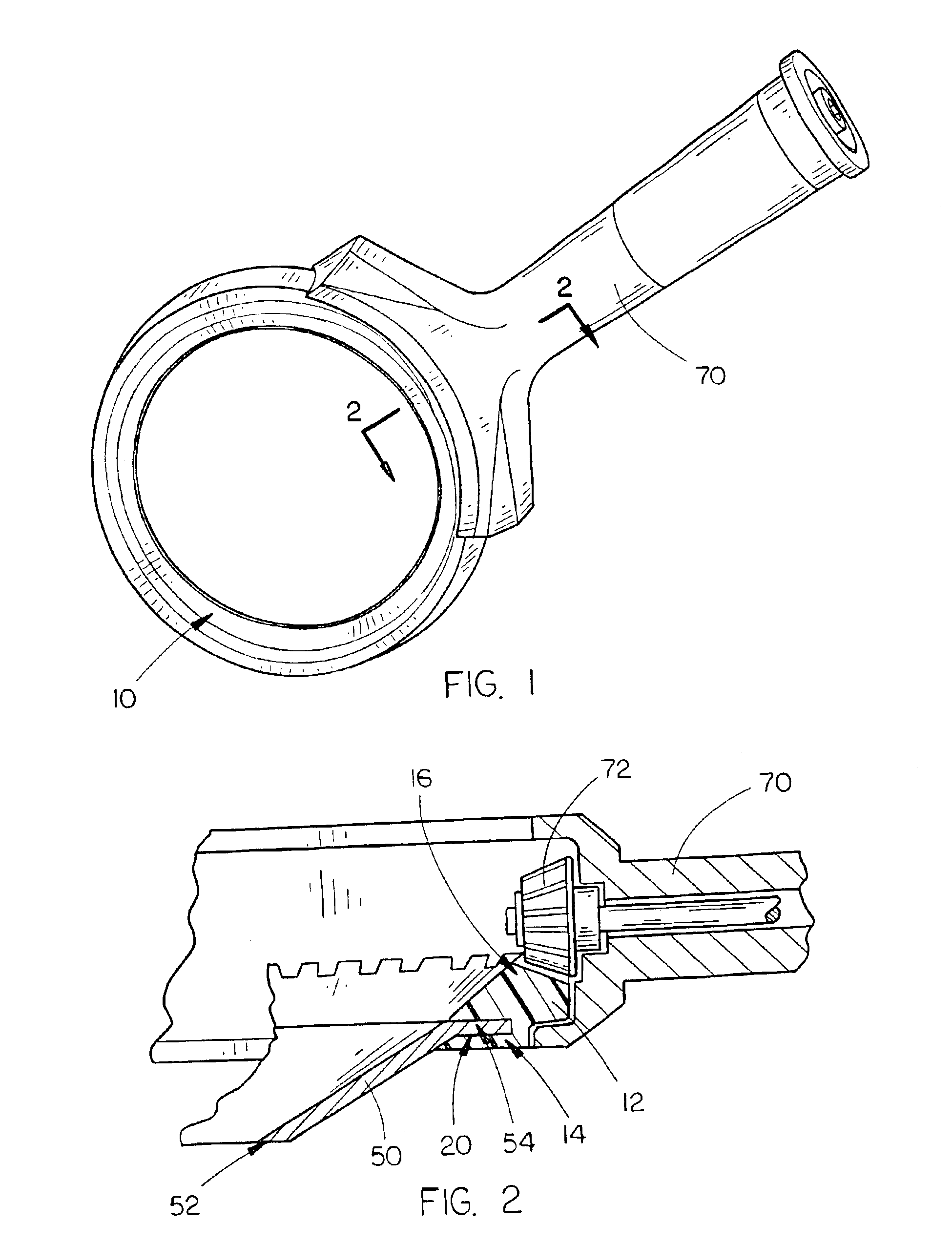
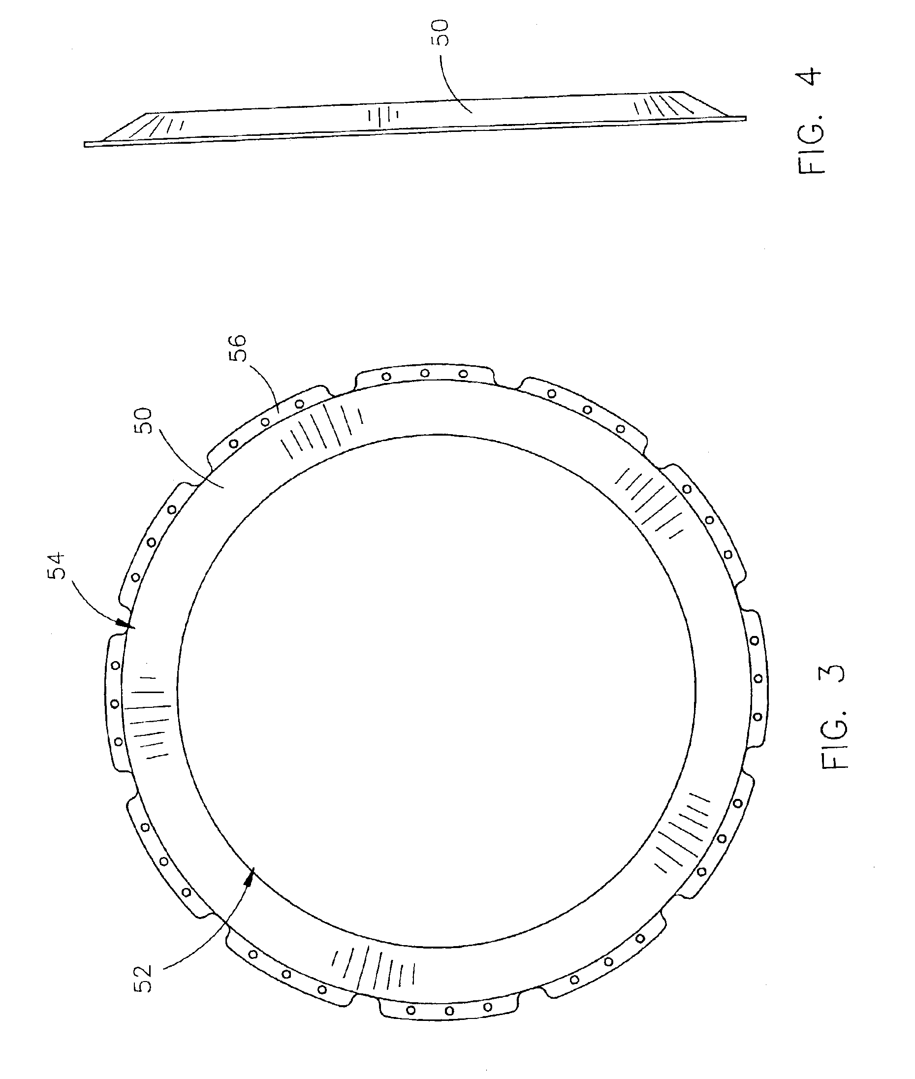
[0023]The molded plastic blade holder 10 of the present invention is shown best in FIGS. 1-10 as including a generally toroidal molded plastic ring 12 which includes a lower blade-engaging section 14 and upper gear-engaging section 16. The toroidal blade 50 would be of the standard type used with boning and defatting knives with which the present invention is intended to be used, and thus would include a sharpened circular lower edge 52 and an upper section 54 which would be engaged by the lower blade-engaging section 14 of toroidal ring 12.

[0024]One of the major problems encountered with the use of the boning and defatting knives currently used in the meat packing industry is that they are extremely noisy and have a great deal of vibration due to the metal on metal meshing of the drive gear with the toothed upper section of the standard defatting blade. This results in increased chances for hearing damage and bodily injury to the person using the device, which, of course, is undesi...


PUM


Abstract

In combination, a toroidal rotary knife blade having a sharpened circular lower edge and an upper blade holder engagement section and a blade holder for the toroidal rotary knife blade. The blade holder includes a generally toroidal blade holding ring having an upper gear-engaging section including a plurality of gear teeth formed thereon for intermeshing with a drive gear and a lower blade engagement and retention section adapted to receive and retain the toroidal rotary knife blade therein. The blade holding ring is constructed of material selected from the group consisting of plastic, polyvinyl chloride, polyethylene, polypropylene, polystyrene, vinyl, and polyethylene terephthalate. Finally, the generally toroidal blade holding ring is operative to reduce noise and vibration emitted therefrom during rotation of the generally toroidal blade holding ring by a drive gear due to the use of plastic construction materials.

Description

CROSS-REFERENCE TO RELATED APPLICATION[0001]This application claims priority to the filing date of related provisional patent application Ser. No. 60 / 349,199 filed on Jan. 15, 2002.BACKGROUND OF THE INVENTION[0002]1. Technical Field[0003]The present invention is directed to blade holding devices and, more particularly, to a toroidal molded plastic blade holder for use with toroidal blades commonly used on defatting and boning knives in the meat packing industry, the molded plastic blade holder including a lower blade-engaging section and an upper gear-engaging section.[0004]2. Description of the Prior Art[0005]The meat packing and processing industry has become increasingly important as the world population continues to grow thereby increasing the need for meat and meat products. As a result of the increased demand for meat, the meat packing industry had to become more efficient in its meat processing and packing operations. Through the use of improved technology and “assembly-line”...

Claims


Application Information

Patent Timeline
IPC IPC(8): B26B25/00B26D1/00
CPCB26B25/002B26D1/0006B26D2001/002Y10T83/9403Y10T83/9464
Inventor LONG, JOHN W.ROSS, DALE R.
Owner LONG JOHN W
Why Eureka
Try Eureka