Split four stroke engine

Inactive Publication Date: 2005-04-19
SKADERI GRUP LLC
View PDF74 Cites 54 Cited by
  • Summary
  • Abstract
  • Description
  • Claims
  • Application Information

AI Technical Summary

Benefits of technology

[0035]The present invention offers advantages and alternatives over the prior art by providing a four-stroke cycle internal combustion engine having a pair of pistons in which one piston of the pair is used for the intake and compression strokes and another piston of the pair

Problems solved by technology

This is because as the compression ratios of SI or CI engines increase substantially beyond the above ranges, several other problems occur which outweigh the advantages gained.
Also problems of premature ignition begin to occur, especially in SI engines.
However, none were able to offer greater efficiencies or other significant advantages, which would replace the standard engine 10 exemplified above.
Unfortunately, transfer of gas in all prior art engines of a split piston design always requires work, which reduces efficiency.
Additionally, the added expansion from the thermal chamber to the engine cylinder of Koenig also reduced compression ratio.
Moreover, the cooling and re-heating of the gas, back and forth through the thermal chamber did not provide enough of an advantage to overcome the losses incurred during the gas transfer process.
Therefore, the Koenig patent lost efficiency and compression ratio relative to the standard engine 10.
Unfortunately, as will be discussed in greater detail hereinafter, the greater the advantage an offset was to the power stroke was also accompanied by an associated increasing disadvantage to the compre

Method used


Image

  • Split four stroke engine
  • Split four stroke engine
  • Split four stroke engine

Examples


Embodiment Construction

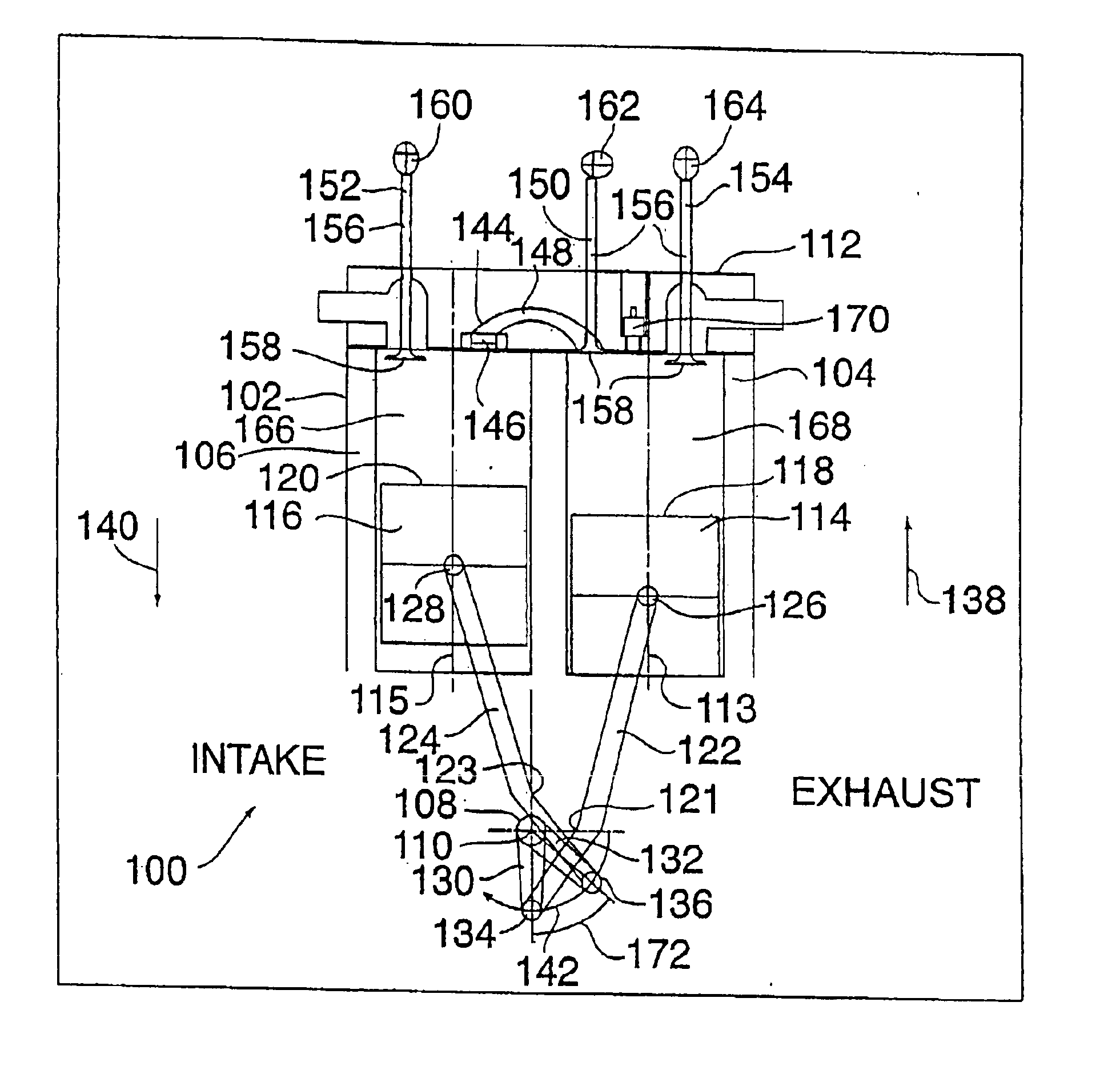
[0049]Referring to FIG. 7, an exemplary embodiment of a four stroke internal combustion engine in accordance with the present invention is shown generally at 100. The engine 100 includes an engine block 102 having a first cylinder 104 and a second cylinder 106 extending therethrough. A crankshaft 108 is journaled for rotation about a crankshaft axis 110 (extending perpendicular to the plane of the paper).

[0050]The engine block 102 is the main structural member of the engine 100 and extends upward from the crankshaft 108 to the junction with the cylinder head 112. The engine block 102 serves as the structural framework of the engine 100 and typically carries the mounting pad by which the engine is supported in the chassis (not shown). The engine block 102 is generally a casting with appropriate machined surfaces and threaded holes for attaching the cylinder head 112 and other units of the engine 100.

[0051]The cylinders 104 and 106 are openings, typically of generally circular cross s...


PUM


Abstract

An engine includes a crankshaft, rotating about a crankshaft axis of the engine. A power piston is slidably received within a first cylinder and is operatively connected to the crankshaft via first linkage system. The power piston reciprocates through a power stroke and an exhaust stroke of a four stroke cycle during a single rotation of the crankshaft. A compression piston is slidably received within a second cylinder and operatively connected to the crankshaft via second linkage system. The first and second linkage systems share no common mechanical link. The compression piston reciprocates through an intake stroke and a compression stroke of the same four stroke cycle during the same revolution of the crankshaft. The power piston leads the compression piston by a phase shift angle that is substantially equal to or greater than zero degrees and less than 30 degrees.

Description

CROSS REFERENCE TO RELATED APPLICATIONS[0001]This patent application is a continuation application of U.S. application Ser. No. 10 / 139,981, filed May 7, 2002 now U.S. Pat. No. 6,609,371, entitled “SPLIT FOUR STROKE ENGINE”, herein incorporated by reference in its entirety, which is a continuation application of U.S. application Ser. No. 09 / 909,594 (now U.S. Pat. No. 6,543,225), filed Jul. 20, 2001, entitled “SPLIT FOUR STROKE CYCLE INTERNAL COMBUSTION ENGINE”, herein incorporated by reference in its entirety.FIELD OF THE INVENTION[0002]The present invention relates to internal combustion engines. More specifically, the present invention relates to a four-stroke cycle internal combustion engine having a pair of offset pistons in which one piston of the pair is used for the intake and compression strokes and another piston of the pair is used for the power and exhaust strokes, with each four stroke cycle being completed in one revolution of the crankshaft.BACKGROUND OF THE INVENTION[0...

Claims


Application Information

Patent Timeline
IPC IPC(8): F02B75/02F02B41/00F02B41/04F02B33/22B60K6/20F02B41/06F02B75/00F02B75/18F02B75/22F02B75/32F02F7/00F02G1/053
CPCF02B33/22F02B41/04F02B41/06F02B75/02F02B75/32F02F7/0019F02G1/0535F02B75/228Y02T10/14F02B2075/027Y02T10/12
Inventor SCUDERI, CARMELO J.
Owner SKADERI GRUP LLC
Why Eureka
Try Eureka