Temperature controlled burner apparatus

a burner and temperature control technology, applied in the field of gas grills, can solve the problems of space temperature, affecting the cooking space temperature, and less well suited to gas grills

a burner and temperature control technology, applied in the field of gas grills, can solve the problems of space temperature, affecting the cooking space temperature, and less well suited to gas grills

US6881055B2Inactive Publication Date: 2005-04-19ADEMCO INC

Image

  • Temperature controlled burner apparatus
  • Temperature controlled burner apparatus
  • Temperature controlled burner apparatus

Examples


Embodiment Construction

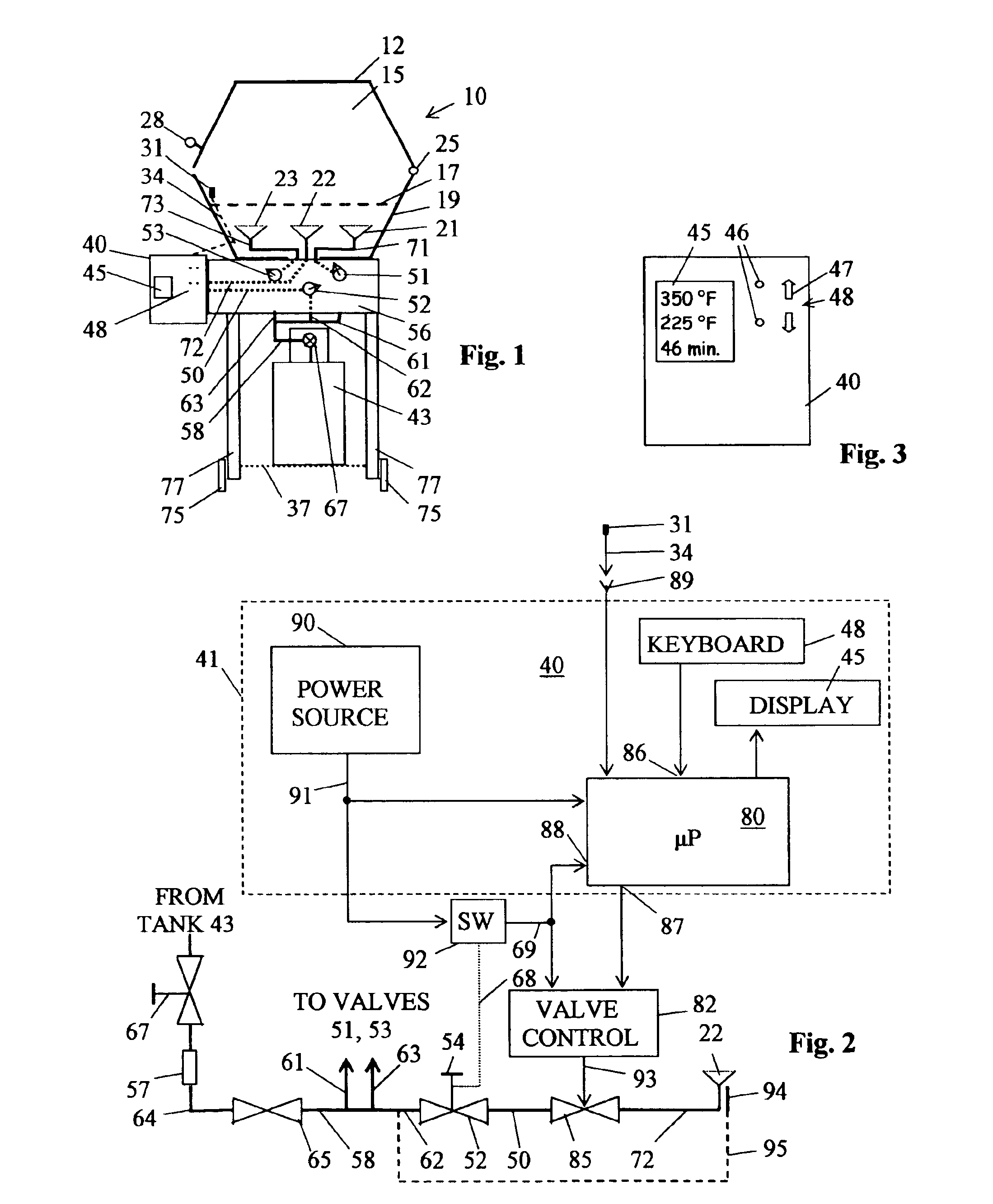
[0020]FIG. 1 shows in a sketch view, the side of a gas grill 10 similar to that found in back yards throughout the country. A typical gas grill 10 may be perhaps 24 in. (61 cm.) wide (normal to the view of FIG. 1) and 18 in. (46 cm.) deep (horizontal dimension of grill 10 as shown in FIG. 1), although the dimensions may vary substantially from these. Grill 10 has a cooking space or enclosure 15 formed within a shell-like base portion 19 and cover 12. A hinge 25 allows the cover 12 to be pivoted clockwise as shown in FIG. 1 to open the grill 10 to provide access to the cooking space. Food to be cooked is placed on a grate 17 mounted within cooking space 15. A handle 28 allows cover 12 to be opened without burning the chef's hand.

[0021]A frame comprising a deck 56 and four legs 77 (only two being shown in FIG. 1) supports base portion 19. Wheels 75 attached to bottom ends of two of the legs 77 allow the entire grill 10 to be easily rolled from one place to another. A bracket 37 suppor...


PUM


Abstract

A system for controlling temperature in an enclosure operates in a low heat or a high heat mode with flame always present. The presently intended use is for providing a cooking grill with a controlled temperature cooking space. An electrically controlled valve having high flow rate and low flow rate settings is interposed in the fuel line for at least one of the burners in the grill. A temperature sensor signals cooking space temperature to a controller that may be a microprocessor. The system includes a keyboard allowing the user to communicate a selected set point to the microprocessor and the microprocessor communicates status to a display. The microprocessor selects the setting of the electrically controlled valve. In a preferred embodiment, the electrically controlled valve is placed in series fuel flow with one of the manually adjustable valves commonly found on cooking grills.

Description

CROSS REFERENCE TO RELATED APPLICATION[0001]A related application (hereafter, the Munsterhuis application) is entitled “Diaphragm-Operated Fluid Flow Control Valve Providing a Plurality of Flow Levels”, is filed on the same date as this application by Wim Munsterhuis, and has a common assignee with this application.BACKGROUND OF THE INVENTION[0002]The gas grill is a well-known home appliance. A gas grill typically includes an enclosure having a base portion mounted on a support frame. A cooking grate for supporting food to be cooked is mounted near the top of the base portion. Burner elements are mounted beneath the grate. A clamshell cover is hinged along the back edge of the base portion and designed to mate with the base portion, so that the cover can be lowered to define and enclose a cooking space and lifted to allow access to food cooking on the grate.[0003]If the grill uses LP gas for fuel, a support frame fixed to the grill holds the common LP (propane) gas tank. The support...

Claims


Application Information

Patent Timeline
19 Apr 2005
Publication
US6881055B2
IPC
F23N5/02; F23N1/00
CPC
F23N5/022; F23N1/00; F23N2041/08; F23N2025/12; F23N2023/08; F23N2225/12; F23N2223/08; F23N2241/08
Inventors
BIRD, DOUGLAS D.