
Method for the operation of a multiple clutching device and a power shift transmission

a clutching device and transmission technology, applied in the direction of gearing, hybrid vehicles, vehicle sub-unit features, etc., can solve the problems of unsatisfactory intermediate acceleration or intermediate deceleration, unfavorable driving and passenger comfort, etc., to reduce friction work, reduce heat input, and reduce the overall amount of friction work

Inactive Publication Date: 2005-04-19
ZF SACHS AG
View PDF2 Cites 55 Cited by
  • Summary
  • Abstract
  • Description
  • Claims
  • Application Information

AI Technical Summary

Benefits of technology

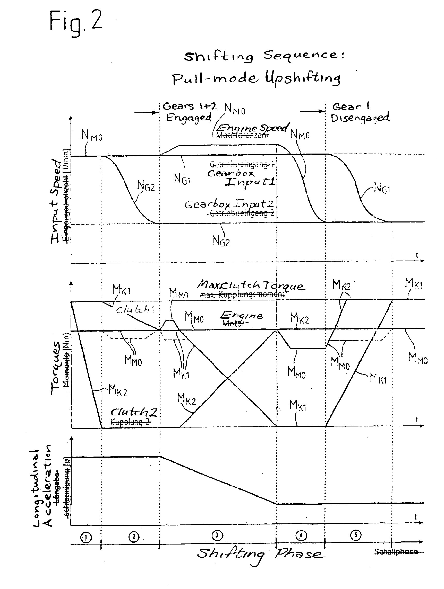
[0018]According to the inventive proposal, it is provided, for example, that, by means of active intervention in engine management or by the exertion of an active influence on the power output stage of the drive train (possibly an internal combustion engine) and possibly by means of the appropriate activation of the auxiliary unit, the torque (possibly the engine torque) delivered by the torque-generating arrangement is controlled in such a way that torque fluctuations occurring at the power takeoff element as a result of unavoidable acceleration and deceleration methods of the engine and / or of the gearbox input shafts (in general, as a result of unavoidable positive and negative acceleration methods) are compensated. As a result of this compensation, the goal of a monotonically rising or monotonically falling longitudinal acceleration can be achieved.
[0065]bringing the clutch arrangement assigned to the target gear into a partially engaged state corresponding to the partial engagement of the clutch arrangement, in which an acceleration torque can be transmitted, so that, by means of the positive drive torque transmitted by this clutch arrangement, the gearbox input shaft assigned to the target gear accelerates along with the drive unit itself toward a synchronous speed assigned to the target gear. With respect to the engagement of the target gear, it is proposed specifically in this connection that the target gear be engaged when the speed of the gearbox input shaft assigned to the target gear is essentially equal to the synchronous speed or has approached the synchronous speed to within a predetermined threshold range of the speed differential. This has the result of decreasing the load on the synchronizing devices of the gearbox without making it necessary to accept an interruption in the pulling or pushing force.

Problems solved by technology

As a result, there can be undesirable intermediate accelerations or intermediate decelerations during the course of shifting.
These make the ride less comfortable for the driver and the passengers during the shifting operation.

Method used


Image

  • Method for the operation of a multiple clutching device and a power shift transmission
  • Method for the operation of a multiple clutching device and a power shift transmission
  • Method for the operation of a multiple clutching device and a power shift transmission

Examples


Embodiment Construction

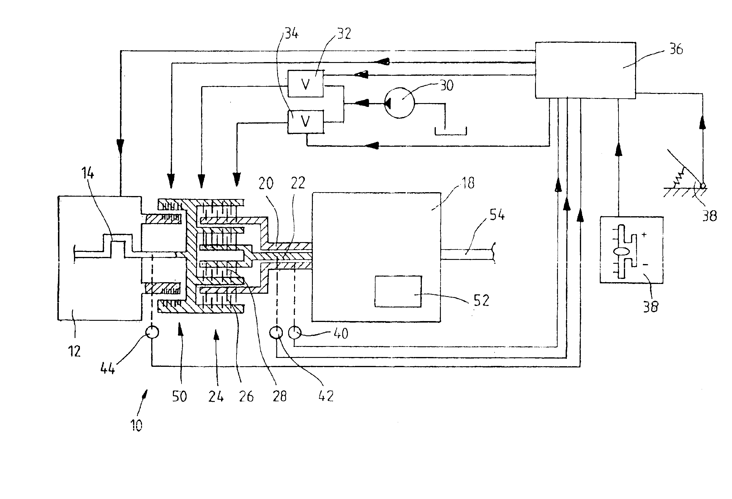
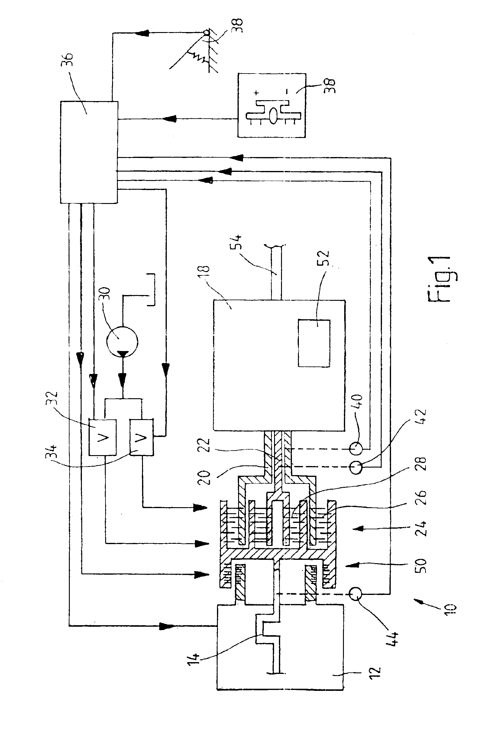
[0089]FIG. 1 shows an example of a drive train 10 of a motor vehicle. The drive train has a drive unit 12 in the form of a combustion engine, especially an internal combustion engine, as indicated by the symbol for a crankshaft 14. A so-called power-shift gearbox 18 with two concentric gearbox input shafts 20 and 22 is connected by a double clutch 24 to the engine 12. The double clutch 24 comprises two clutch arrangements 26 and 28, one of which is assigned to the gearbox input shaft 20, the other to the gearbox input shaft 22. The exemplary embodiment shows wet-running disk clutch arrangements, each of which is actuated hydraulically by its own hydraulic slave cylinder (not shown), integrated into the double clutch. An appropriate hydraulic pump 30 is indicated schematically. A cooling oil circuit and its cooling oil pump, etc., assigned to the double clutch are not shown. Suitable double-clutch designs are described in, for example, DE 100 04 179 A1.

[0090]The two clutch arrangemen...


PUM


Abstract

In either a pull-mode operating state or a push-mode operating state, a clutch arrangement assigned to the first gearbox input shaft and a clutch arrangement assigned to the second gearbox input shaft are actuated in such a way and a torque-generating arrangement comprising a drive unit is controlled in such a way that, when a shift is to be made between a first gear assigned to a first gearbox input shaft and a second gear assigned to a second gearbox input shaft, at least one of the following criteria with respect to the shifting sequence comprising the shift in question is fulfilled:(1) during the shifting sequence, the torque present at the gearbox output shaft is at least approximately constant or changes monotonically;(2) during the shifting sequence, the vehicle accelerates in an essentially monotonically increasing or in an essentially monotonically decreasing manner.

Description

PRIORITY CLAIM[0001]This is a U.S. national stage of application No. PCT / EP01 / 15192, filed on 21 Dec. 2001. Priority is claimed on that application and on the following applications: Country: Germany, Application No.: 101 01 176.8, Filed: 12 Jan. 2001, Country: Germany, Application No.: 101 48 429.1, Filed: 01 Oct. 2001; Country: Germany, Application No.: 101 60 308.8, Filed: 07 Dec. 2001.BACKGROUND OF THE INVENTION[0002]1. Field of the Invention[0003]The invention pertains to a method for operating a drive train belonging to a motor vehicle, the drive train being provided with:[0004]a torque-generating arrangement, which comprises at least one drive unit, possibly in the form of an internal combustion engine, and possibly an auxiliary unit for generating an auxiliary torque;[0005]a gearbox (especially a power-shift gearbox) with a synchronizing device and with at least two gearbox input shafts and at least one gearbox output shaft, where a first gearbox input shaft is assigned to a...

Claims


Application Information

Patent Timeline
Patent Type & Authority Patents(United States)
IPC IPC(8): B60K6/04B60K6/00F16D48/00F16H61/04F16D25/00F16D25/12F16D48/02F16H3/00F16H61/688F16H61/68B60K6/485B60K6/547B60W10/10B60W30/18
CPCB60K6/485B60W10/02B60W10/10B60W10/113B60W30/18B60W30/19F16D25/123F16D48/0206F16H61/0437B60K6/547Y10T477/6403B60K2741/225B60K2741/286B60L2240/423B60L2240/486B60W20/00B60W30/18118B60W2510/105B60W2710/083B60W2710/105B60Y2400/428F16H3/006F16H61/688F16H63/46F16H63/502F16H2306/48F16H2312/00F16H2312/06Y02T10/6226F16H2059/148Y10S903/945Y10S903/919Y02T10/642Y10T477/6407Y10T74/19233B60W10/06B60W30/1819F16D2048/0275F16D48/062F16D2500/1024F16D2500/10412F16D2500/3021F16D2500/3067F16D2500/30816F16D2500/3101F16D2500/3108F16D2500/3144F16D2500/31466F16D2500/50653F16D2500/70252F16D2500/7027F16D2500/70282F16D2500/70426F16D2500/7044F16D2300/06Y02T10/62Y02T10/64B60K2006/268B60W30/18027B60W20/40
Inventor KUHSTREBE, JOCHENJOHN, THOMASREUTHAL, RAINERSTRASSER, THOMAS
Owner ZF SACHS AG
Learn More