Thick scintillation plate with internal light collimation

a scintillation plate and collimation technology, applied in the field of medical imaging devices, can solve the problems of reducing image resolution, loss of reconstructed image resolution, and inability to exchange images with different characteristics, so as to achieve effective capture of high energy radiation, reduce light spreading, and improve the effect of resolution

Inactive Publication Date: 2005-04-19
SAINT GOBAIN IND CERAMICS INC
View PDF11 Cites 32 Cited by
  • Summary
  • Abstract
  • Description
  • Claims
  • Application Information

AI Technical Summary

Benefits of technology

[0008]In accordance with the present invention, a scintillation device, such as a gamma camera plate, incorporates a novel crystal feature which permits the achievement of satisfactory resolution for both low and high energy radiation. The crystal is sufficiently thick to effectively capture the high energy radiation, but is provided on its light output side with an array of light path-modifying partitions which extend partly through the thickness of the crystal. These partitions define individual light collimating cells. These cells reduce the light spreading which would otherwise prevent effective use of the plate for low energy radiation. At the same time, the collimating cells do not significantly interfere with the use of the camera plate for high energy rays and may even improve it. The term “collimate” herein refers to modifying light in the crystal to control its lateral spreading as it travels from a scintillation event location in the crystal bulk to the light output face.

Problems solved by technology

The spreading results in some loss of reconstructed image resolution and is undesirable in that respect, but it is at the same time also necessary to some extent for determination of position information by comparing the signal response of several nearby photomultiplier tubes to the same scintillation event.
This presents a serious tradeoff problem with regard to the choice of thickness for the crystal.
On the other hand, a crystal with an optimum thickness for high energy radiation suffers from excessive light spreading with low energy radiation, thereby reducing the image resolution.
However, this is a costly component which is also closely matched to the associated electrical hardware and software and therefore not easily exchanged for one with different characteristics.

Method used


Image

  • Thick scintillation plate with internal light collimation
  • Thick scintillation plate with internal light collimation
  • Thick scintillation plate with internal light collimation

Examples


Embodiment Construction

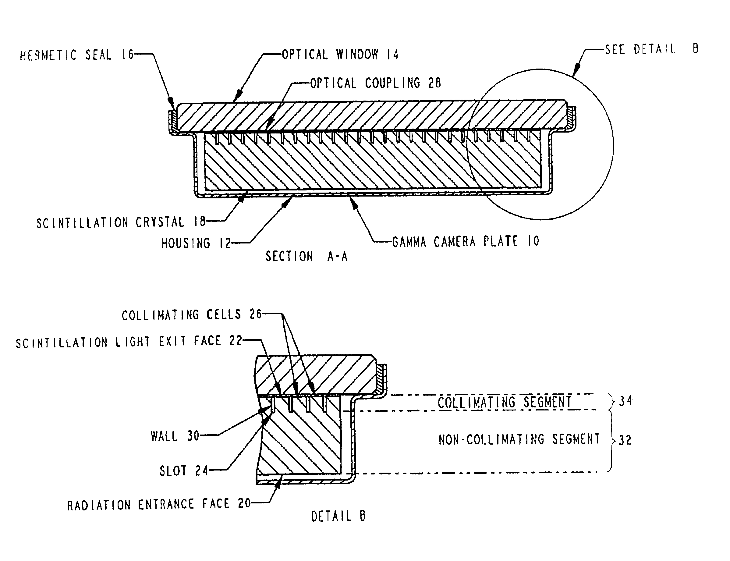
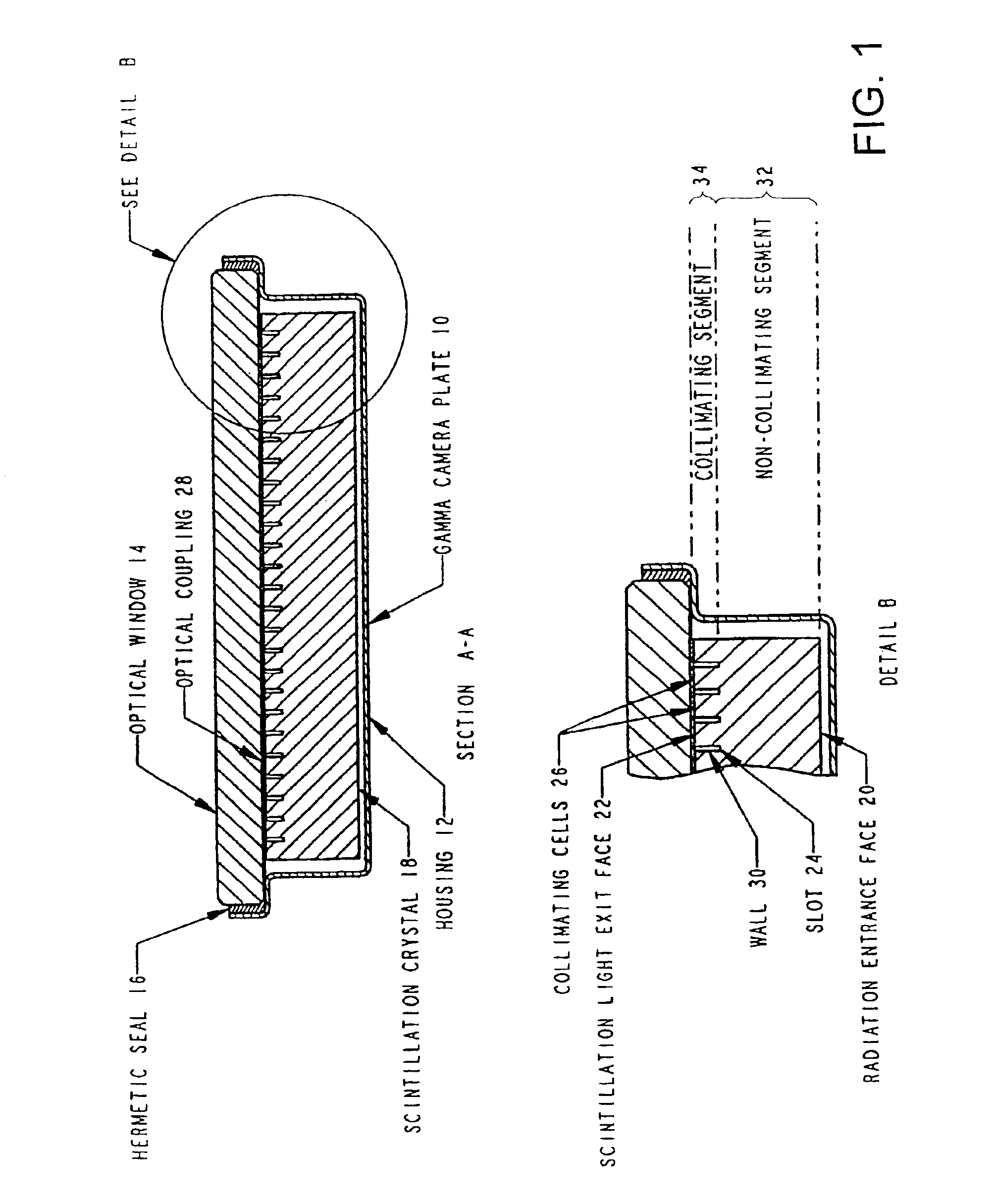
[0012]A preferred embodiment of the present invention is the novel gamma camera plate 10 shown in FIG. 1. The camera plate 10 includes a thin back cap 12 of aluminum to which a glass optical window 14 is assembled with an epoxy hermetic seal 16 to form a sealed housing. Inside the housing is a scintillation crystal 18 about 1.9 cm thick of thallium-activated NaI (sodium iodide) having a radiation entrance face 20 and a light output face 22. The light output face 22 is coupled to the optical window 14 by means of a transparent polymer optical coupling 28.

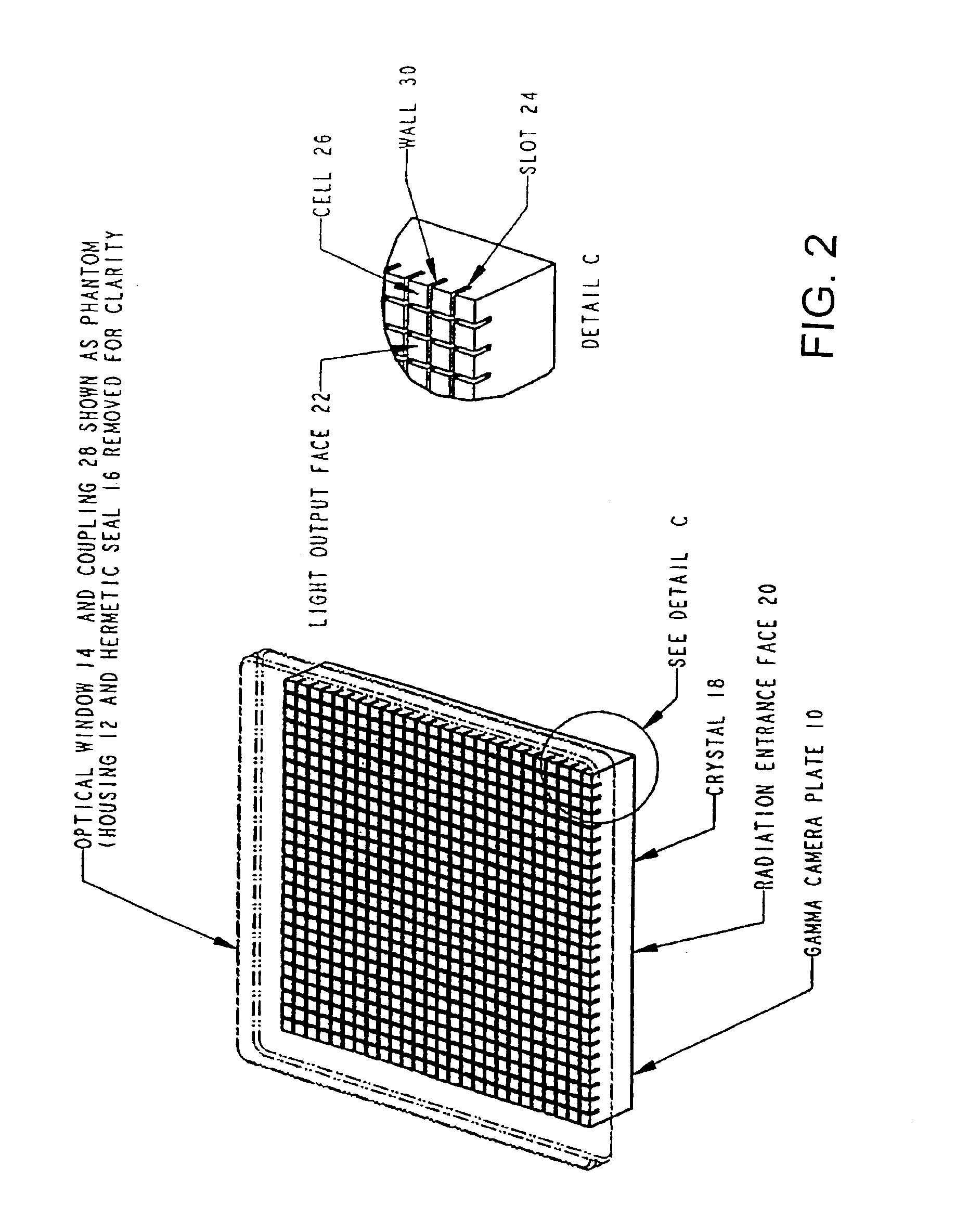
[0013]An orthogonal set of equally-spaced, narrow slots 24 about 1 mm wide spaced from each other a distance of about 6 mm extend about 10 mm from the light output face 22 into the scintillation crystal 18 toward the radiation entrance face 20 to form an orthogonal array of closely-spaced collimating cells 26 which have square cross-sections in a plane parallel to the light output face 22 and have four walls 30 defined by the slots 2...


PUM


Abstract

A gamma camera plate incorporates scintillation crystal which is sufficiently thick to effectively capture high energy radiation. The crystal is provided on its light output side with an array of light path-modifying partitions which extend partly through its thickness. These partitions define individual light collimating cells which reduce the light spreading which would otherwise prevent effective use of the plate for low energy radiation.

Description

CROSS-REFERENCE TO RELATED APPLICATIONS[0001]This application is a continuation of Ser. No. 09 / 517,492, filed Mar. 2, 2000, now U.S. Pat. No. 6,563,121, which claims the benefit of the provisional application No. 60 / 123,959 filed Mar. 12, 1999.FIELD OF THE INVENTION[0002]The invention relates generally to medical imaging devices and more particularly to such devices which use energy conversion devices to obtain an electrical signal in response to gamma radiation.BACKGROUND[0003]Medical imaging is accomplished by inducing a patient with a radiopharmaceutical substance by injection swallowing, inhalation, or other appropriate means. The radioactive isotope of the radiopharmaceutical selectively migrates to the target area tissue to be examined and emits gamma radiation from it. Reference herein to “radiation” is to any ionizing radiation, but typically gamma radiation. The radiation can be sensed and used to generate a reconstructed image of features of the target area tissue to provi...

Claims


Application Information

Patent Timeline
Patent Type & Authority Patents(United States)
IPC IPC(8): G01J1/00G01T1/20G01T1/202G01T1/24G01T1/00G01T1/164
CPCG01T1/1644G01T1/202G01T1/2002
Inventor SCHREINER, ROBERT S.MATARAZA, GEORGEROZSA, CSABA M.
Owner SAINT GOBAIN IND CERAMICS INC
Why Eureka
Try Eureka