Tunable clock distribution system for reducing power dissipation

a clock distribution and power dissipation technology, applied in the field of integrated circuits, can solve the problems of increasing the power consumption of synchronous ic b>100/b>, requiring additional costly cooling systems, and requiring integrated circuits, so as to achieve the effect of reducing minimizing the power dissipation of the clock distribution network

Active Publication Date: 2005-04-19
XILINX INC
View PDF5 Cites 107 Cited by
  • Summary
  • Abstract
  • Description
  • Claims
  • Application Information

AI Technical Summary

Benefits of technology

[0006]The present invention provides a tunable clock distribution system with an adjustable resonant frequency in an integrated circuit which is tuned towards the frequency of the clock signal on a clock distribution network. As the resonant frequency of the tunable clock distribution system approaches the clock

Problems solved by technology

However, increasing the frequency of clock signal S_CLK greatly increases the power consumption of synchronous IC 100.
Excess heat may damage integrated circuits, thus additional costly cooling systems may be required for a high frequency integrated circuit.
Furthermore, many integrated cir

Method used


Image

  • Tunable clock distribution system for reducing power dissipation
  • Tunable clock distribution system for reducing power dissipation
  • Tunable clock distribution system for reducing power dissipation

Examples


Embodiment Construction

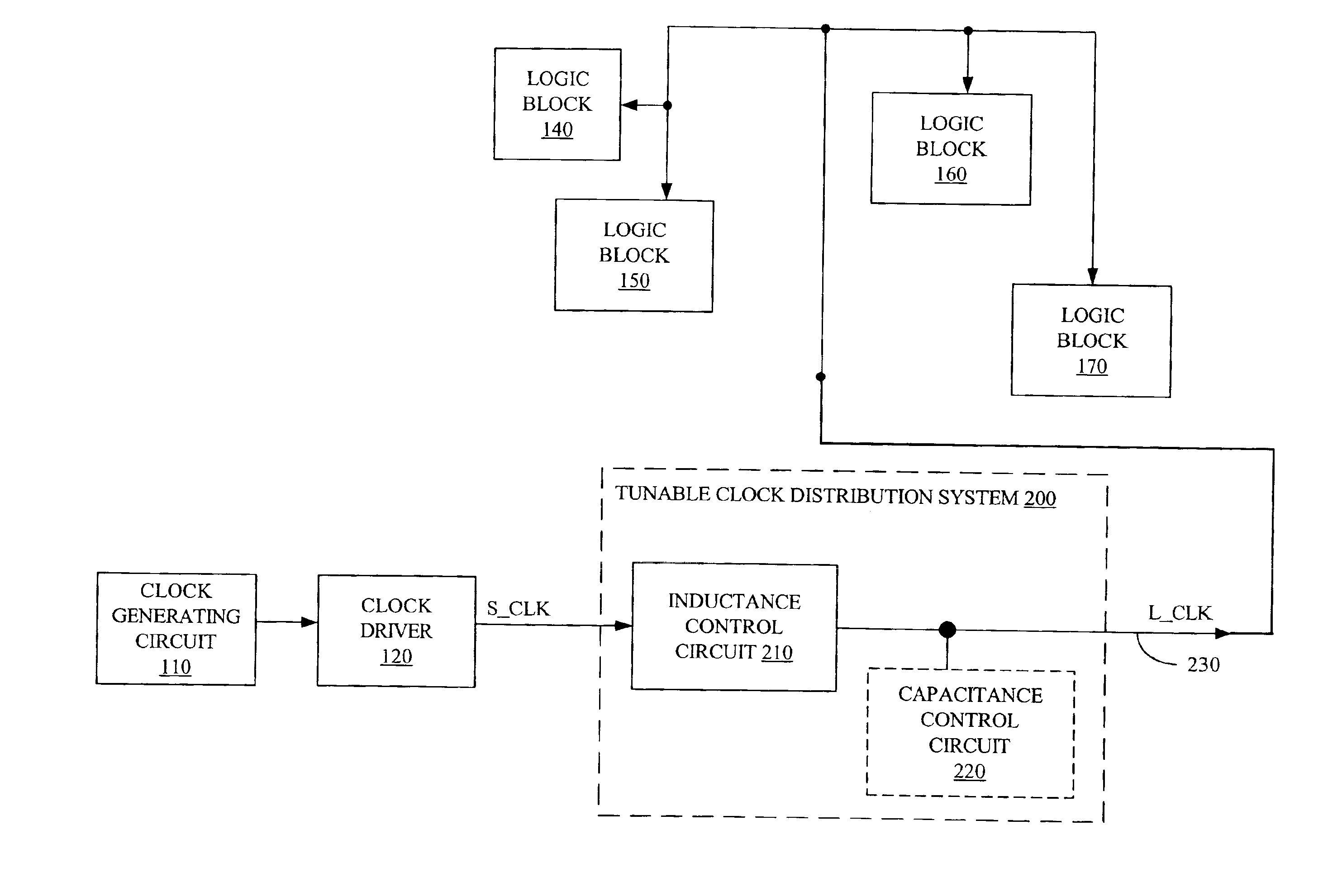
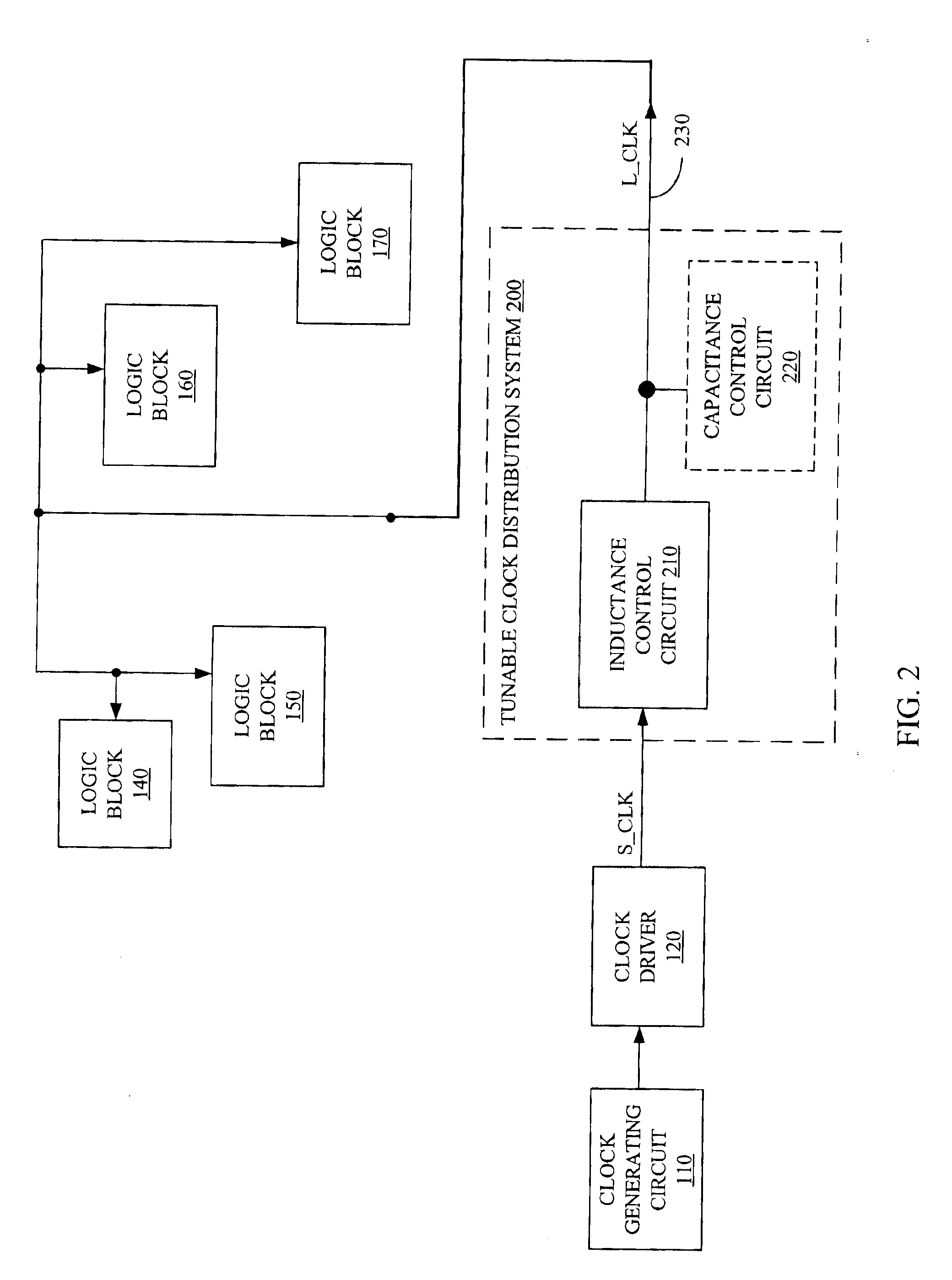
[0018]FIG. 2 is a block diagram of a tunable clock distribution system 200 in accordance with one embodiment of the present invention. Tunable clock distribution circuit 200 is coupled to clock driver 120 which is coupled to clock generating circuit 110. Tunable clock distribution circuit 200 includes clock distribution network 230, an inductance control circuit 210 and an optional capacitance control circuit 220. Specifically, clock driver 120 drives system clock signal S_CLK through inductance control circuit 210 onto a clock distribution network 230, where clock distribution network 230 distributes a clock signal (L_CLK) to logic blocks 140-170, that may be part of a FPGA. For clarity, the clock signal on clock distribution network 230 after inductance control circuit 210 is referred to as inducted clock signal L_CLK. Optional capacitance control circuit 220 is coupled between clock distribution network 230 and ground.

[0019]Inductance control circuit 210 is configured to adjust t...


PUM


Abstract

A tunable clock distribution system is used to minimize the power dissipation of a clock distribution network in an integrated circuit. The tunable clock distribution system provides a tunable inductance on the clock distribution network to adjust a resonant frequency in the tunable clock distribution system. The inductance is tuned so that the resonant frequency of the tunable clock distribution system approaches the frequency of the clock signal on the clock distribution network. As the resonant frequency of the tunable clock distribution system approaches the frequency of the clock signal, the power dissipation of the clock distribution network decreases. Some embodiments also provide a tunable capacitance on the clock distribution network to adjust the resonant frequency of the tunable clock distribution system.

Description

FIELD OF THE INVENTION[0001]The present invention relates to integrated circuits using clock signals. More specifically, the present invention relates to tunable clock distribution circuits for reducing the power dissipation of a clock distribution network.BACKGROUND OF THE INVENTION[0002]Synchronous integrated circuits (IC) rely on one or more clock signals to synchronize elements across the integrated circuit. Typically, one or more clock signals are distributed across the system on one or more clock distribution networks. FIG. 1 illustrates a typical synchronous IC 100, which can be for example, a microprocessor, a programmable logic device (PLD) such as a field programmable gate array (FPGA), a digital signal processor, or a graphics controller. Specifically, synchronous IC 100 has a clock generating circuit 110, a clock driver 120, and a clock distribution network 130, and logic blocks 140, 150, 160, and 170. Specifically, clock generating circuit 110 drives a clock signal CLK ...

Claims


Application Information

Patent Timeline
IPC IPC(8): H03K3/012H03K3/00G06F1/10
CPCG06F1/10H03K3/012
Inventor CONN, ROBERT O.LAWMAN, GARY R.KINGSLEY, CHRISTOPHER H.LESEA, AUSTIN H.
Owner XILINX INC
Why Eureka
Try Eureka