Method of encoding a digital data stream

a digital data and data stream technology, applied in the field of data recording, can solve the problems of spoiled phase accuracy of this channel, data becomes irreparably damaged, and it is not easy to make a digital plug-compatible equivalent of the above longitudinal multi-track instrumentation recorder, so as to avoid cumulative errors in determining the position of these transitions and achieve high accuracy

Inactive Publication Date: 2005-04-19
KNOTT JOHN +1
View PDF6 Cites 5 Cited by
  • Summary
  • Abstract
  • Description
  • Claims
  • Application Information

AI Technical Summary

Benefits of technology

[0025]The present invention can enable the position of transitions within frequency shift keyed data streams to be described to an accuracy of 1% using only ten recorder bits per data bit. This can be achieved using a highly accurate master clock to determine the positions in time of all transitions in the input data stream, and cumulative errors in determining the positions of these transitions can thereby be avoided.
[0028]The present invention can also provide suppression of spurious noise in the input digital data signals.
[0029]Locking the frequency of the single master clock to a frequency standard can also enable recorded data to be replayed at exactly the rate at which it was recorded.

Problems solved by technology

However, as the above requirements for recording digital data streams indicate, it is not a simple task to make a digital plug-compatible equivalent of the above longitudinal multi-track instrumentation recorders.
In theory a clock can be regenerated from the data, but if the phase lock loop usually used by clock recovery devices is disturbed by noise, extra or missing clock transitions will be produced, and this will usually spoil the phase accuracy of this channel from then on.
However, if the disturbance occurred during recording of the data, the data becomes irreparably damaged.
However, this introduces small phase errors.
In addition it suffers with the problems associated with the clock recovery devices referred to above.
Furthermore, such filters have the disadvantage that they impose a limit on the rate of change of originally sharp transitions, resulting inevitably in ringing caused by these sharp transitions.
It is also debatable as to whether clock recovery devices used with conventional instrumentation recorders will function correctly with the resulting degraded waveforms, thereby calling into question the ability to provide true plug-compatibility.
However, the above techniques involve the consumption of 10 recording bits per data bit just to produce a less than perfect representation of the input signal.
There are further problems associated with using a computer to analyse digital data streams which have been recorded with a sample clock rate close to the Nyquist rate.
Clearly this would place a far greater burden on the analysing computer than a perfectly timed and square edged signal.
This would then produce a digital representation of the waveform, but the edges of the waveform could be displaced from their true positions by up to 10%, placing additional burdens on the clock recovery device.
In addition, ten bits do not fit conveniently into either computer bytes or words, which makes analysis by computer difficult.
More samples would help, but this would be at the expense of recording duration.
Time division is not the only possible multiplexing scheme.

Method used


Image

  • Method of encoding a digital data stream
  • Method of encoding a digital data stream
  • Method of encoding a digital data stream

Examples


Embodiment Construction

[0030]An embodiment of the present invention will now be described with reference to the accompanying drawings in which:

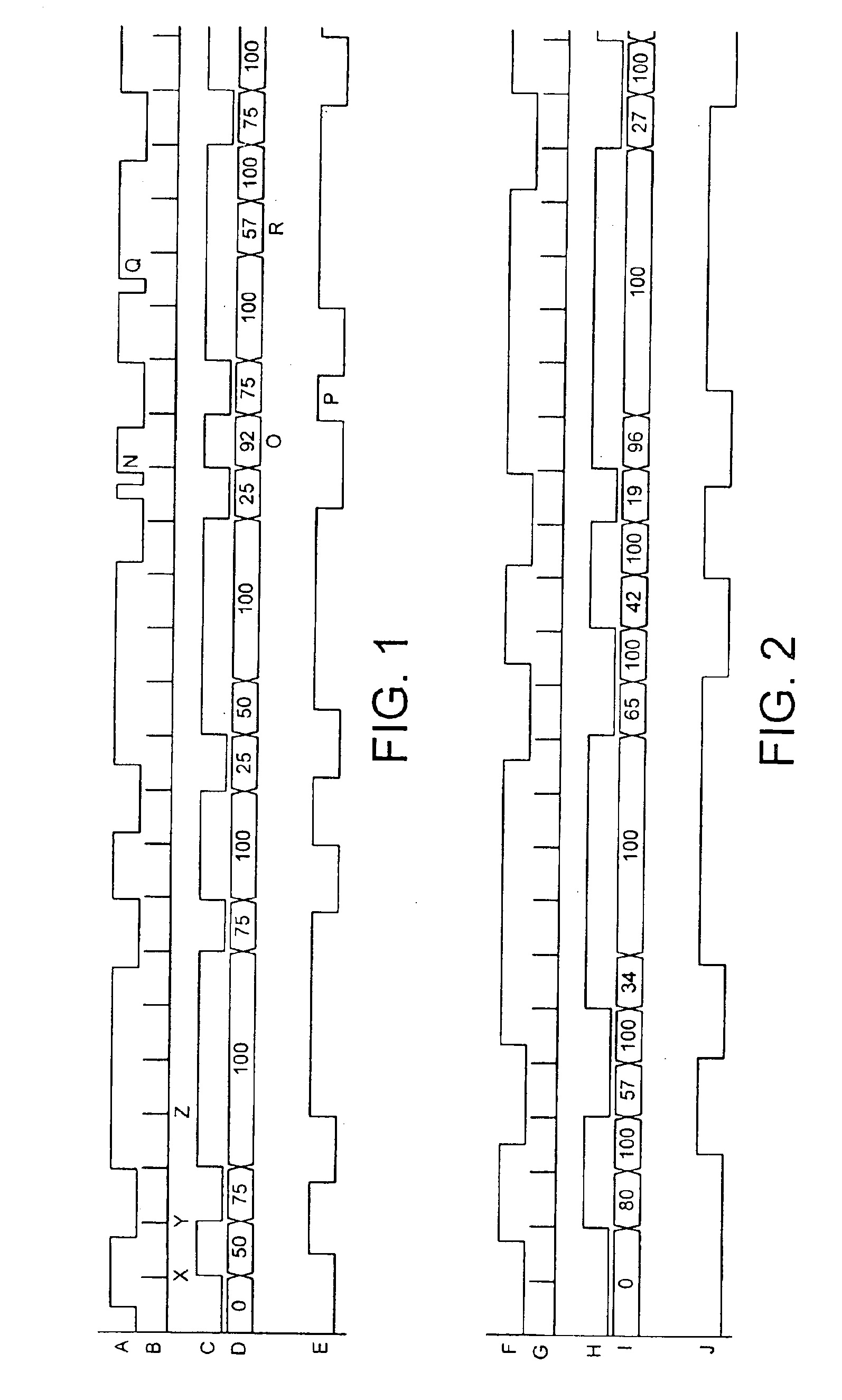
[0031]FIG. 1 shows timing charts for a first input data stream and the effect of coding it using the present invention;

[0032]FIG. 2 shows timing charts for a second input data stream unrelated to that of FIG. 1, and the effect of coding it using the present invention;

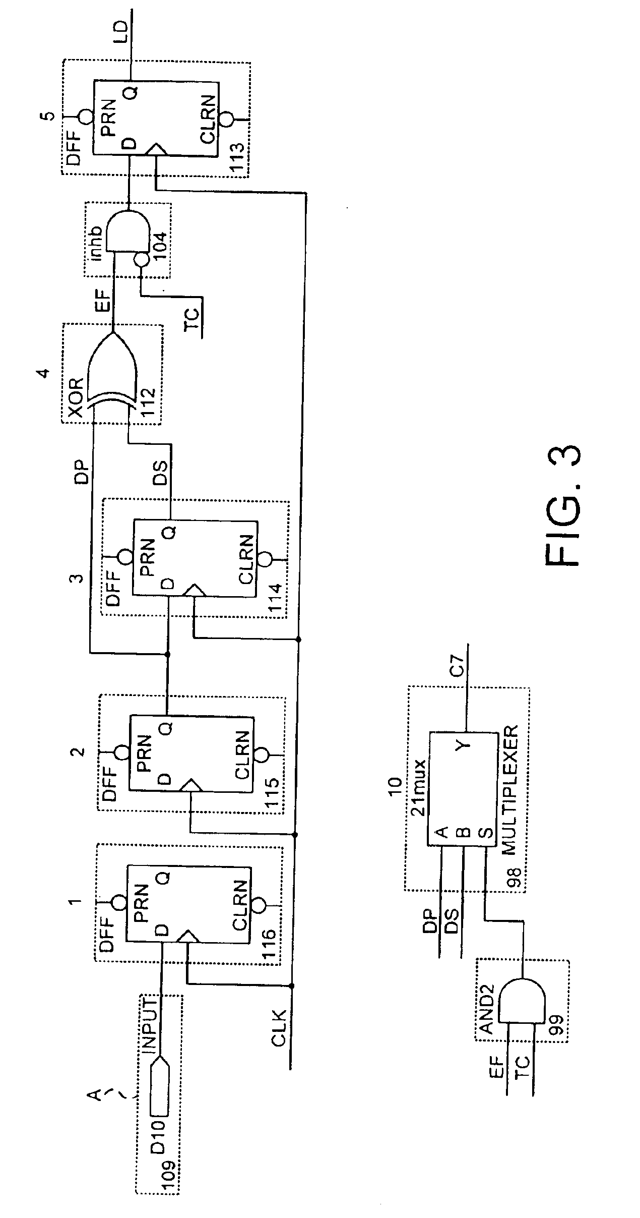
[0033]FIG. 3 shows a circuit diagram for a device effecting coding of the data stream of FIG. 1 using a method in accordance with the present invention;

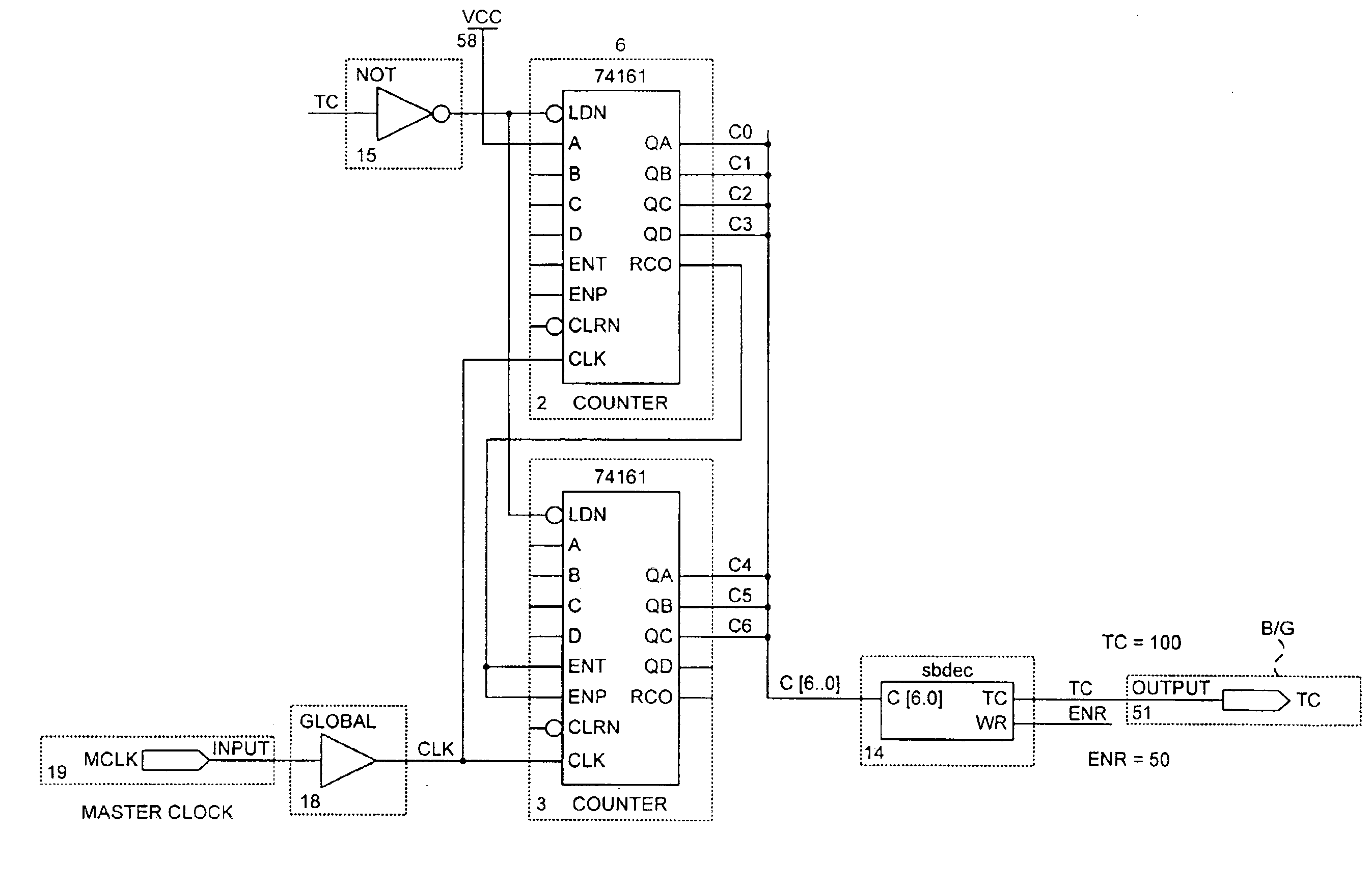
[0034]FIG. 4 shows a circuit diagram of counters used to effect coding in accordance with the present invention;

[0035]FIG. 5 corresponds to FIG. 3 showing coding of the data stream of FIG. 2, the circuitry of FIG. 3 being reduced to a single symbol;

[0036]FIG. 6 shows a circuit for decoding the coded data stream produced with reference to FIG. 3; and

[0037]FIG. 7 shows a circuit for decoding the coded data stream produced with reference to FIG. 5.

[0038]A ...


PUM

PropertyMeasurementUnit
frequencyaaaaaaaaaa
time domainaaaaaaaaaa
timeaaaaaaaaaa

Abstract

A method of encoding a digital data stream which comprises providing a first stream of clock pulses at a first rate; deriving a second stream of clock pulses from the first stream at a second rate which is an integer sub-multiple of the first rate and less than the minimum bit rate in the data stream; monitoring the data stream for changes in level therein; counting pulses in the first stream starting with the occurrence of a pulse in the second stream; capturing the pulse count when a change in level in the data stream is detected or when the next pulse in the second stream of clock pulses occurs; and upon the occurrence of this pulse in the second stream producing a time domain descriptor of the data by combining the count obtained with information as to the direction of the change in level in the data input stream.

Description

FIELD OF THE INVENTION[0001]This invention concerns data recording and particularly the recording of multiple PCM telemetry data streams.BACKGROUND TO THE INVENTION[0002]The recording of telemetry data streams transmitted via radio links from remote sensors is carried out for various purposes by utilities and government agencies. These streams can be in analogue form, in which information is encoded by modulation of a carrier, or by frequency shift keying (FSK), in which the data is used to change the frequency of a carrier.[0003]The remote sensors generating such data streams often send data at rates which vary slightly from one sensor to another (plesio synchronous).[0004]Recording data from a number of sensors, often including both analogue and digital data, requires preservation of the phase relationship between the sensor data streams whatever method of recording is used.[0005]Traditionally, data streams from remote sensors have been recorded on longitudinal multi-track instrum...

Claims


Application Information

Patent Timeline
Patent Type & Authority Patents(United States)
IPC IPC(8): G11B20/14G11B20/10H04L25/493
CPCG11B20/10H04L25/493G11B20/14
Inventor KNOTT, JOHN
Owner KNOTT JOHN
Why Eureka
Try Eureka