Laser pulse shaping device

a technology of pulse shaping and laser, which is applied in the direction of electrical equipment, instruments, optics, etc., can solve the problems of increasing the amount of original laser power lost in the truncation process,

Inactive Publication Date: 2005-04-19
ROKE MANOR RES LTD
View PDF13 Cites 6 Cited by
  • Summary
  • Abstract
  • Description
  • Claims
  • Application Information

AI Technical Summary

Benefits of technology

[0009]It is therefore an object of the invention to enable a constant power truncated pulse to be generated without the additional power loss associated with simply using a narrower ultra-short pulse.

Problems solved by technology

However, this approach has the disadvantage that the amount of original laser power that is lost, in the truncation process increases as the ultra-short pulse is shortened.

Method used


Image

  • Laser pulse shaping device
  • Laser pulse shaping device
  • Laser pulse shaping device

Examples


second embodiment

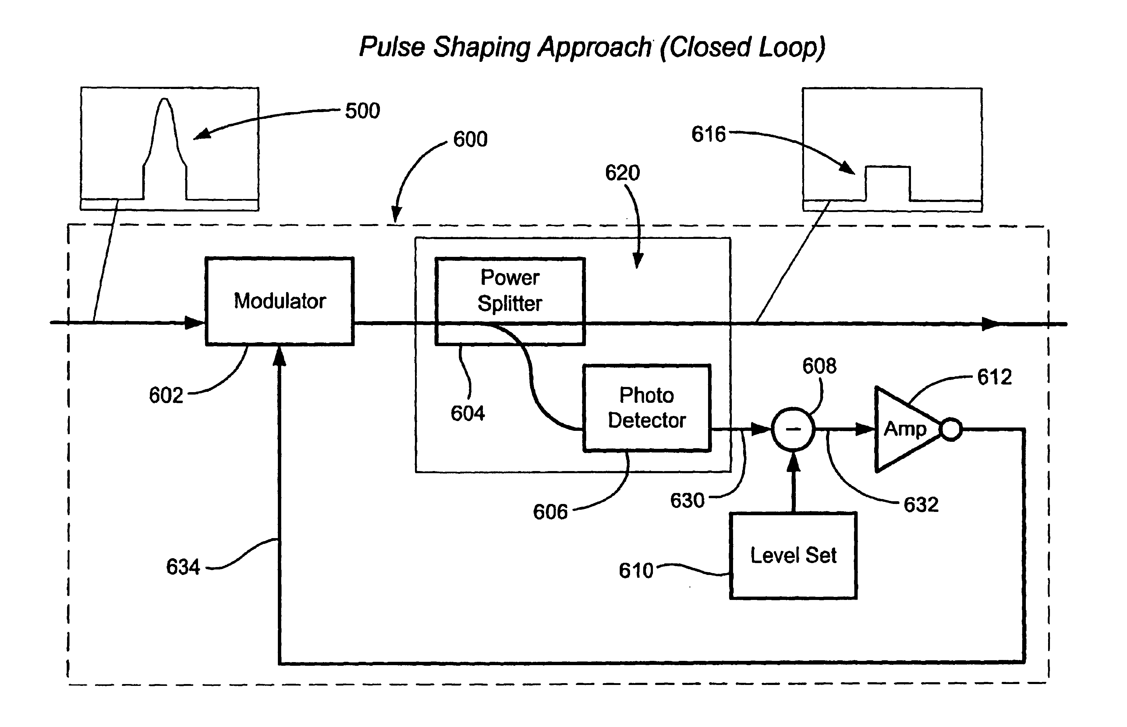
[0039]the present invention implements a feed-forward approach 800 as illustrated in FIG. 8. In feed-forward, the pulse power is measured before the pulse shape is corrected, using a sampling means 620. The power measurement 830 is then applied to an amplifier 802 with a controllable gain 804. The output of the amplifier 832 is then used to drive a modulator 806, the attenuation of which is proportional to the applied voltage.

[0040]In the feed-forward configuration, the gain 804 must be adjusted to give the best results. Once set, the gain 804 must be maintained as the system temperature changes. In addition, if the pre-correction pulse characteristics change, the gain 804 may have to be adjusted. In both circumstances it may be necessary to incorporate a further sampling means after the modulator to monitor the quality of the pulse correction and to adjust the amplifier gain as necessary.

[0041]It may not be possible or convenient to use a modulator that has a linear relationship be...

third embodiment

[0042]the present invention, involves the use of an optical limiting amplifier or a limiting medium. Suitable limiting media include liquid crystals and neodymium-doped glasses and semiconductors, indeed any of a range of materials whose absorption depends upon the optical power level. This configuration is illustrated in FIG. 9. The truncated pulse 500 passes through an optical limiting amplifier 902 that saturates at a certain power level. The power level is then effectively capped at the saturation level.

[0043]The effectiveness of the limiting configuration depends on the saturation characteristics of the amplifier or medium, for example whether the medium resonates or the saturation response is too slow. In addition the saturation point of the amplifier may itself have a wavelength dependence which will translate into a variation of the pulse level.

[0044]It will be understood that the present invention applies to pulse shaping of optical pulses in general rather than solely to t...


PUM

PropertyMeasurementUnit
wavelengthaaaaaaaaaa
wavelengthsaaaaaaaaaa

Abstract

A pulse shaping apparatus for shaping an input optical pulse into an output optical pulse having substantially constant optical power, includes a modulator that acts upon the input optical pulse in response to a control signal. A sampling unit samples a portion of the input or output pulse and generates a sample signal that corresponds to the optical power of the input or output optical pulse. In a preferred embodiment, the sampling unit includes a power splitter that splits off sample portion of the input or output pulse, and directs the sample portion to the photodetector which generates the sample signal. Processing of the sample signal may be performed in either an analog or digital form.

Description

BACKGROUND OF THE INVENTION[0001]The present invention relates to a pulse shaping means. In particular the pulse shaping means is suitable for shaping the mater pulse associated with an optical backplane device.[0002]The invention has application in the development of new architectures for optical switching applied to high-speed digital communication routers / switches.[0003]UK Patent Application No. 9930163.2—“Data Compression Apparatus and Method Therefor” describes the operation of an optical backplane, for example an optical fiber, in an optical switching system. In particular, 9930163.2 discloses a compression method for converting packets of data at 10 Gbits / s to compressed packets at 1.28 Tbits / s. The compressed packets are then time multiplexed onto the fiber optic backplane of a device such as an IP router or ATM switch.[0004]An essential part of a compression method is the generation of a chirped master laser pulse. This is typically a 5 nanosecond (ns) pulse that chirps ove...

Claims


Application Information

Patent Timeline
Patent Type & Authority Patents(United States)
IPC IPC(8): H04B10/155H04B10/152G02F1/03H04B10/50H04B10/508
CPCH04B10/505H04B10/508H04B10/50593H04B10/50572
Inventor MANSBRIDGE, JOHN
Owner ROKE MANOR RES LTD
Why Eureka
Try Eureka