
Packet data analysis with efficient buffering scheme

a packet data and buffering technology, applied in data switching networks, multiplex communication, instruments, etc., can solve the problems of low performance of centralized packet analysis schemes and difficult scaling, and achieve the effect of increasing performan

Inactive Publication Date: 2005-04-19
CISCO TECH INC
View PDF3 Cites 59 Cited by
  • Summary
  • Abstract
  • Description
  • Claims
  • Application Information

AI Technical Summary

Benefits of technology

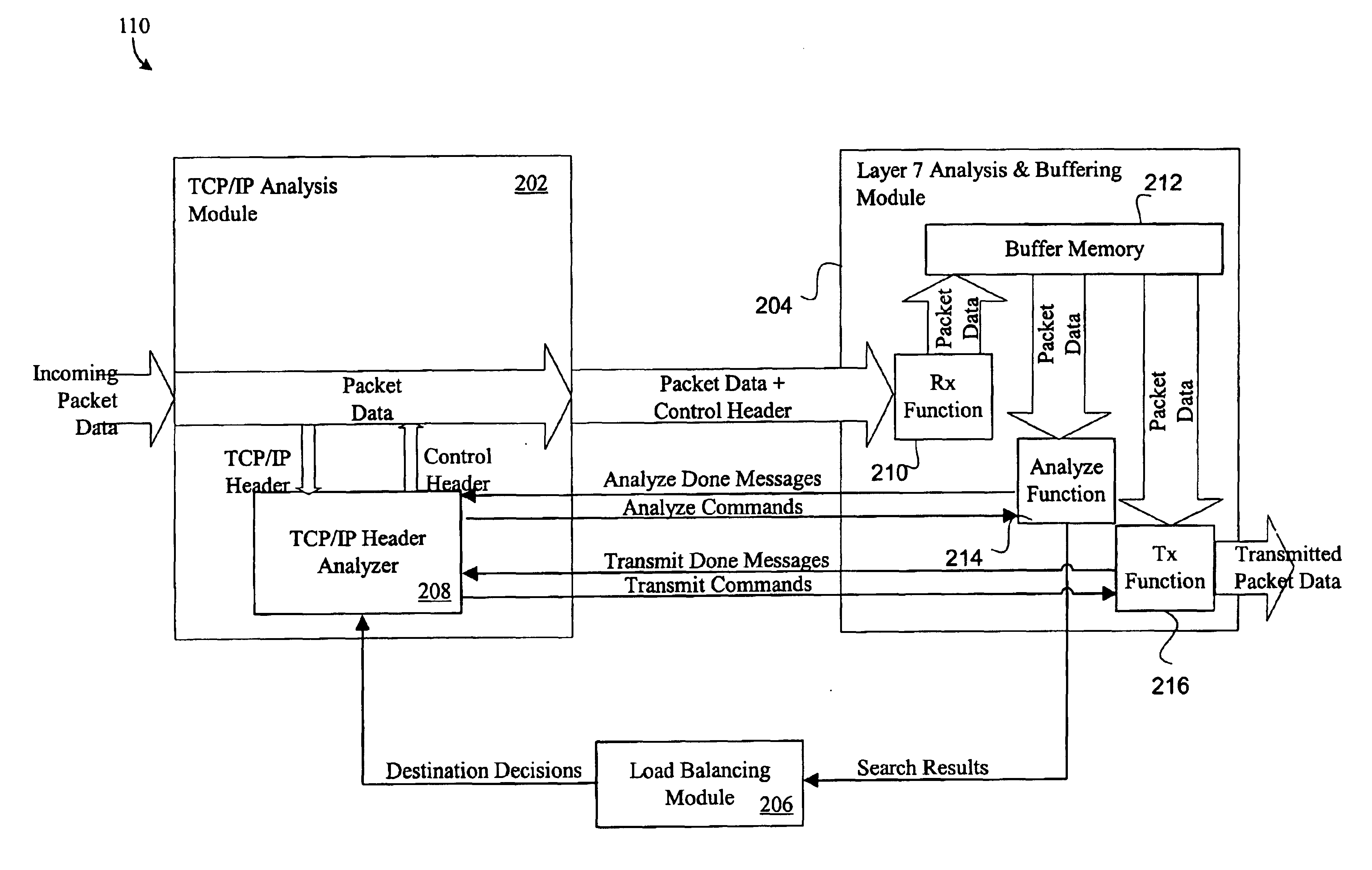
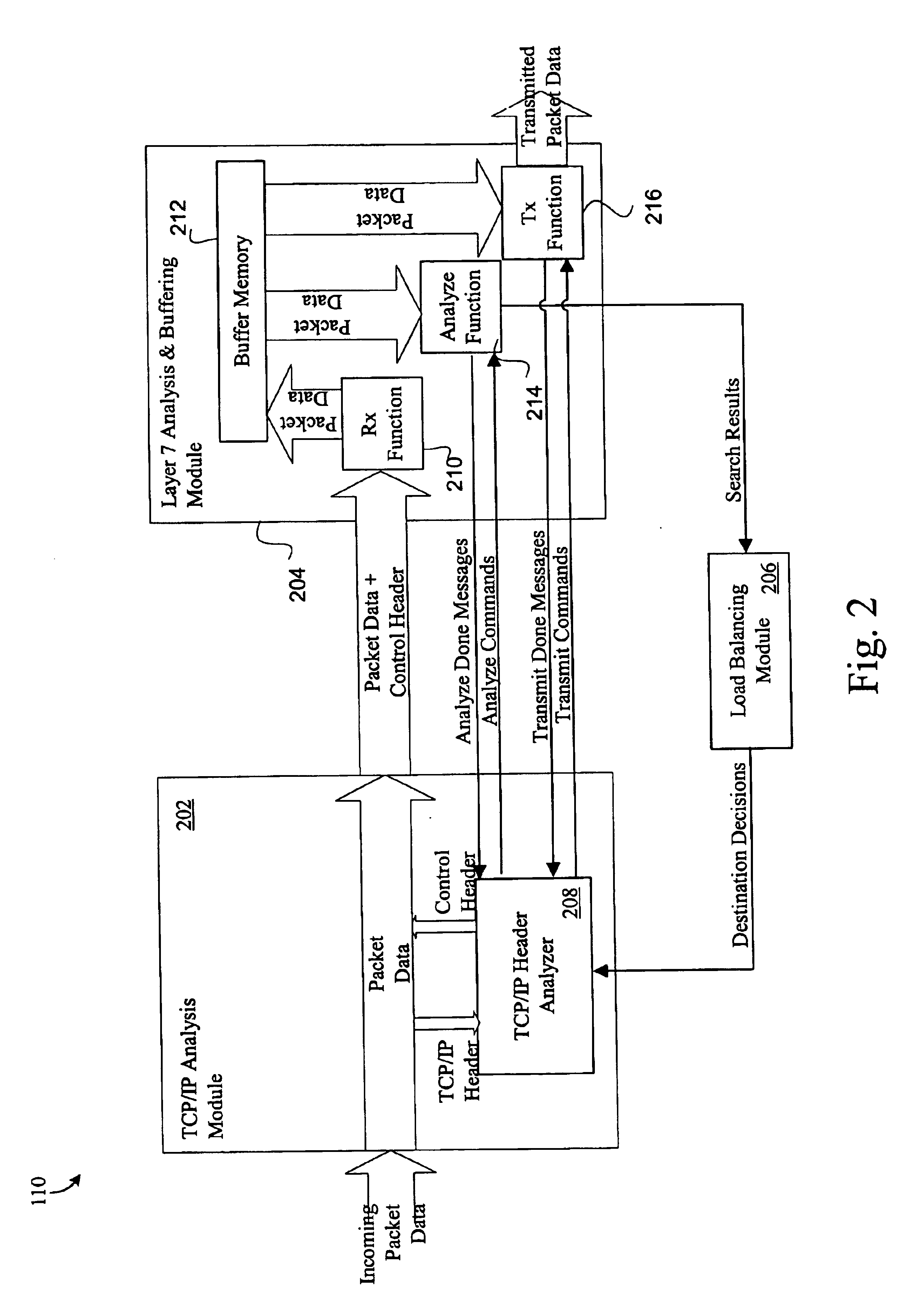
[0006]Accordingly, the present invention provides apparatus and methods for buffering packets within a system that distributes different tasks (e.g., packet reordering, datagram reassembly, and Layer 7 packet analysis) into different modules. Such a distributed system may result in increased performance. In general terms, the present invention represents an improvement over conventional packet buffering mechanisms in distributed Layer 7 switches by providing a centralized buffer and centralized buffer manager for a plurality of distributed packet data analysis procedures. In one implementation, a TCP module is configured to perform buffer management. That is, the TCP module knows which addresses within the buffer are free and which are allocated. The TCP module also includes at least one data structure that holds a plurality of references to the buffer's addresses. In this implementation, a Layer 7 Module does the buffering. The TCP Module instructs the Layer 7 Module through one or more commands to perform various buffering procedures, such as wiring data to the buffer and reading data from the buffer.
[0013]Several embodiments of a centralized buffer configuration may provide relatively low overhead costs in terms of buffer management, allocation, and deallocation, read / write complexities and cycle time usage (e.g., low memory bandwidth usage), as compared to a distributed buffer scheme. In a distributed buffer scheme, one buffer may become full, while another buffer has a relatively large amount of free space. In such a case, the module with excess free buffer space may consume resources processing data, only to have the results of this processing be discarded due to lack of space in another buffer. Furthermore, when buffering is performed in multiple modules, each module must perform similar buffer management and data buffering operations. This duplication of similar functions represents greater expenditure of resources to perform the same data analysis task.

Problems solved by technology

Such a centralized packet analysis scheme typically provides low performance and is also difficult to scale.

Method used


Image

  • Packet data analysis with efficient buffering scheme
  • Packet data analysis with efficient buffering scheme
  • Packet data analysis with efficient buffering scheme

Examples


Embodiment Construction

[0019]Reference will now be made in detail to a specific embodiment of the invention. An example of this embodiment is illustrated in the accompanying drawings. While the invention will be described in conjunction with this specific embodiment, it will be understood that it is not intended to limit the invention to one embodiment. On the contrary, it is intended to cover alternatives, modifications, and equivalents as may be included within the spirit and scope of the invention as defined by the appended claims. In the following description, numerous specific details are set forth in order to provide a thorough understanding of the present invention. The present invention may be practiced without some or all of these specific details. In other instances, well known process operations have not been described in detail in order not to unnecessarily obscure the present invention.

[0020]The buffering mechanisms described further below may be implemented for any suitable applications. In ...


PUM


Abstract

Disclosed is an apparatus employing an efficient buffering scheme for analyzing the Layer 7 content in packet data sent from a first node to a second node within a computer network. The apparatus includes a first device having a buffer and one or more first processors. The apparatus also includes a second device having one or more second processors. The first device is a physically separate device from the second device. The second processor of the second device is configured to manage the buffer of the first device, and the first processor is also configured to analyze packet data accessed from the buffer.

Description

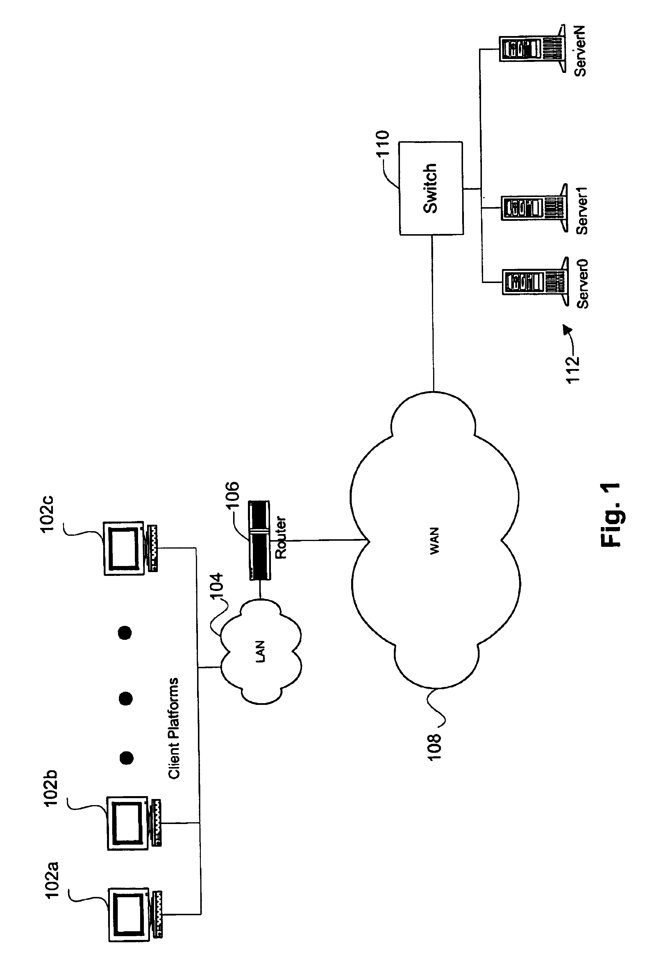
BACKGROUND OF THE INVENTION[0001]The present invention relates to methods and apparatus for analyzing packet data transmitted and received within a network. More specifically, this invention pertains to buffering packet data while packet analysis is being performed or until analysis begins.[0002]In a specific application, packet data is received into a Layer 7 Switch that “sits” in front of a plurality of routers. Layer 7 corresponds to the Open System Interconnect (OSI) “Application Layer.” The Layer 7 Switch may be configured to perform a number of packet analysis procedures on received packet data. By way of specific implementation, IP fragments are stored until all fragments of an IP packet are received. A Session Identifier and a Virtual Server Identifier (VSID) are then determined for packet data received into the switch. For instance, the Session ID is based on the packet data's protocol type, source and destination IP addresses, and source and destination ports. In order to ...

Claims


Application Information

Patent Timeline
IPC IPC(8): H04L29/06H04L29/08H04L12/26
CPCH04L43/18H04L67/06H04L69/329H04L67/1002H04L67/2852H04L67/1029H04L67/02H04L67/1001H04L67/5682
Inventor NELSON, WILLIAM M.
Owner CISCO TECH INC
Learn More