Method of fuel nozzle sizing and sequencing for a gas turbine combustor

a gas turbine and combustor technology, which is applied in the direction of machines/engines, mechanical equipment, lighting and heating apparatus, etc., can solve the problems of combustor wall exposure, affecting the integrity and life of the combustor, and not as stable as the more typical diffusion flame combustion system, etc., to achieve uniform flame temperature distribution, reduce the effect of dynamic pressure level and uniform fluid flow

Inactive Publication Date: 2005-04-26
H2 IP UK LTD
View PDF10 Cites 30 Cited by
  • Summary
  • Abstract
  • Description
  • Claims
  • Application Information

AI Technical Summary

Benefits of technology

[0008]In accordance with the present invention, the dynamic pressure levels are reduced and a more uniform flame temperature distribution is created within a combustion chamber by determining the respective flow characteristics of each of the nozzles and positioning each nozzle at an optimum location on a combustor end cover. The optimum location is determined by a combination of compensating for measured and calculated pressure losses, changes

Problems solved by technology

Since this type of combustion system operates close to the lean flammability limit, combustion is not as stable as the more typical diffusion flame combustion systems.
These pressure oscillations, if not minimized and adequately controlled, can affect the integrity and life of the combustor.
Another issue of concern to operators of premix combustion systems is the effect of prolonged combustor wall exposure to elevated temperatures, especially non-uniform temperature distribution.
Also, the more poorly mixed regions will tend to not burn as completely as the better mixed regions, resulti

Method used


Image

  • Method of fuel nozzle sizing and sequencing for a gas turbine combustor
  • Method of fuel nozzle sizing and sequencing for a gas turbine combustor
  • Method of fuel nozzle sizing and sequencing for a gas turbine combustor

Examples


Embodiment Construction

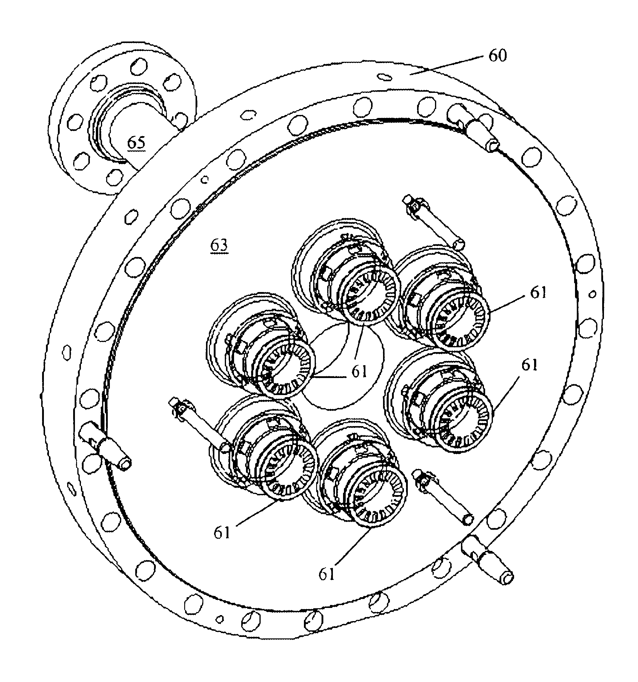
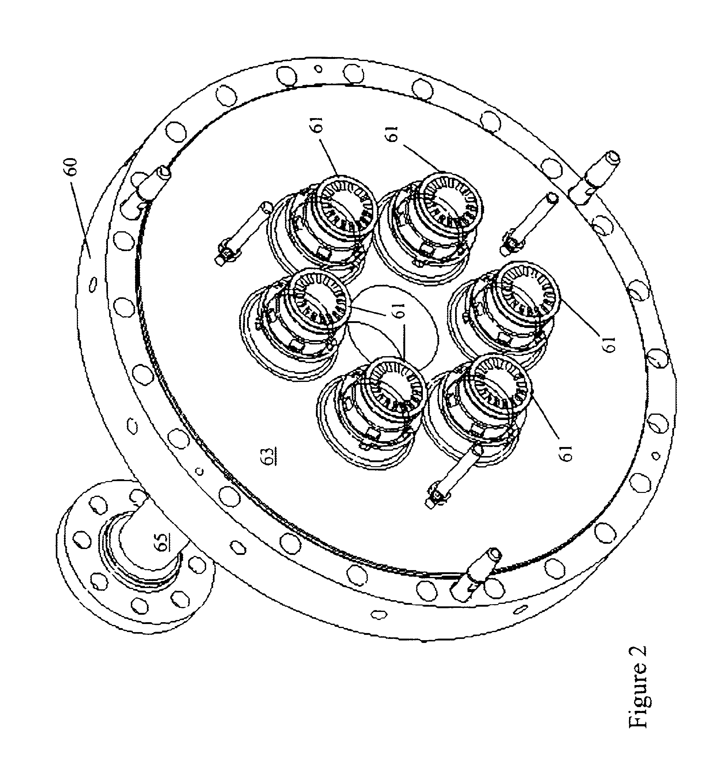
[0016]The present invention, which will now be described in detail, is shown in the accompanying FIGS. 2-4. Referring now to FIG. 2, an end cover 60, which is used to enclose a combustion chamber for a gas turbine engine, is shown in perspective view. End cover 60, which is preferably circular in cross section, is shown containing a plurality of nozzles 61, typically at least two, which are fixed to end cover 60. In order to provide an end cover having generally uniform fuel flow to a combustion chamber, which will result in a more uniform flame temperature throughout the combustor and reduce combustor dynamics, a number of operations must occur to end cover 60 and nozzles 61 before they are assembled on the engine.

[0017]Referring now to FIGS. 2 and 3, an end cover 60 is provided having a first face 62, a second face 63, a first thickness 64 therebetween, a fluid inlet 65, a manifold 66 in fluid communication with fluid inlet 65, a plurality of feed passages 67 in fluid communicatio...


PUM


Abstract

A method for providing a gas turbine engine and a combustor having a more uniform fluid flow is disclosed. For a combustor end cover, individual nozzle flow rates are determined and nozzles positioned on an end cover such that each nozzle injects substantially the same amount of fluid as an adjacent nozzle. As a result, gas temperature variations within the combustor are reduced and combustion dynamics lowered. For a gas turbine engine utilizing a plurality of combustors, individual end cover flow rates are determined and end covers positioned on each combustor relative to the supply inlet of the engine such that each end cover is supplied with a substantially similar flow rate. Other factors including pressure loss and fluid temperature changes are taken into consideration when determining nozzle and end cover positions.

Description

BACKGROUND OF THE INVENTION[0001]1. Field of the Invention[0002]This invention relates to fuel injection system of a gas turbine combustor and more specifically, to a method for balancing fuel flow to a plurality of fuel nozzles and to a plurality of combustor end covers about a gas turbine engine.[0003]2. Description of Related Art[0004]The U.S. Government has enacted requirements for lowering pollution emissions from gas turbine combustion engines, especially nitrogen oxide (NOx) and carbon monoxide (CO). These emissions are of particular concern for land based gas turbine engines that are used to generate electricity since these types of engines usually operate continuously and therefore emit steady amounts of NOx and CO. A variety of measures have been taken to reduce NOx and CO emissions including the use of catalysts, burning cleaner fuels such as natural gas, and improving combustion system efficiency. One of the more significant enhancements to land based gas turbine combust...

Claims


Application Information

Patent Timeline
IPC IPC(8): F02C7/22F23R3/46F23R3/28F23R3/00
CPCF02C7/22F23R3/46F23R3/28F23R2900/00014
Inventor MARTLING, VINCENT C.
Owner H2 IP UK LTD
Why Eureka
Try Eureka