Method for determining the wall thickness and the speed of sound in a tube from reflected and transmitted ultrasound pulses

a technology of ultrasound pulses and tube walls, applied in the field of ultrasonic pulses, or waves, can solve the problems of inconvenient or inaccurate tube thickness, and achieve the effects of avoiding calculation errors, enhancing accuracy, and minimizing or abrogating temperature-related errors

Inactive Publication Date: 2005-04-26
WRIGHT STATE UNIVERSITY
View PDF16 Cites 38 Cited by
  • Summary
  • Abstract
  • Description
  • Claims
  • Application Information

AI Technical Summary

Benefits of technology

[0009]These needs are met by the present invention, where a new method for determining the sound propagation velocity and wall thickness of a tubular workpiece is described. As used in the present context, a tubular workpiece need not be cylindrical in cross-section; it could be elliptical or even rectangular. It will be appreciated by those skilled in the art that the present method could also be used on elongate, non-tubular members, such as cylindrical or elliptical solid rods and related structure. Extraction of the sound velocity and tube thickness from the sensed data obviates the need for using a contact-based method for measuring the tube thickness, which can be either inconvenient or inaccurate under certain conditions. It also avoids calculation errors by utilizing actual measured speed of sound in the tubular workpiece, rather than assuming a fixed, predetermined value. It also extends the use of multiple transducers to objects with complex geometries, such as tubes, where access limitations

Problems solved by technology

Extraction of the sound velocity and tube thickness from the sensed data obviates the need for using a contact-base

Method used


Image

  • Method for determining the wall thickness and the speed of sound in a tube from reflected and transmitted ultrasound pulses
  • Method for determining the wall thickness and the speed of sound in a tube from reflected and transmitted ultrasound pulses
  • Method for determining the wall thickness and the speed of sound in a tube from reflected and transmitted ultrasound pulses

Examples


Embodiment Construction

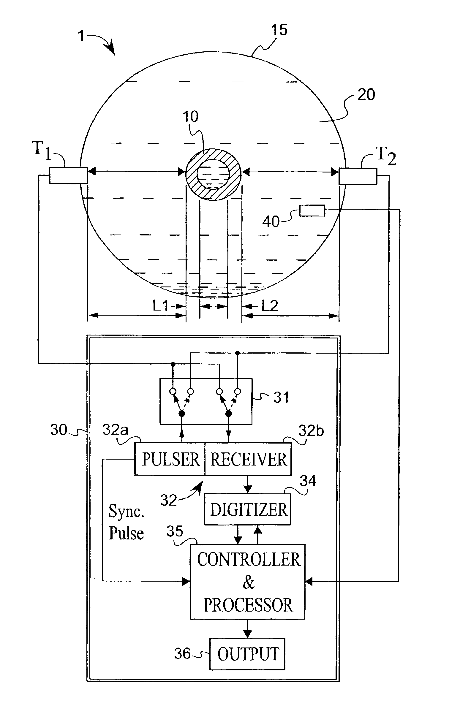
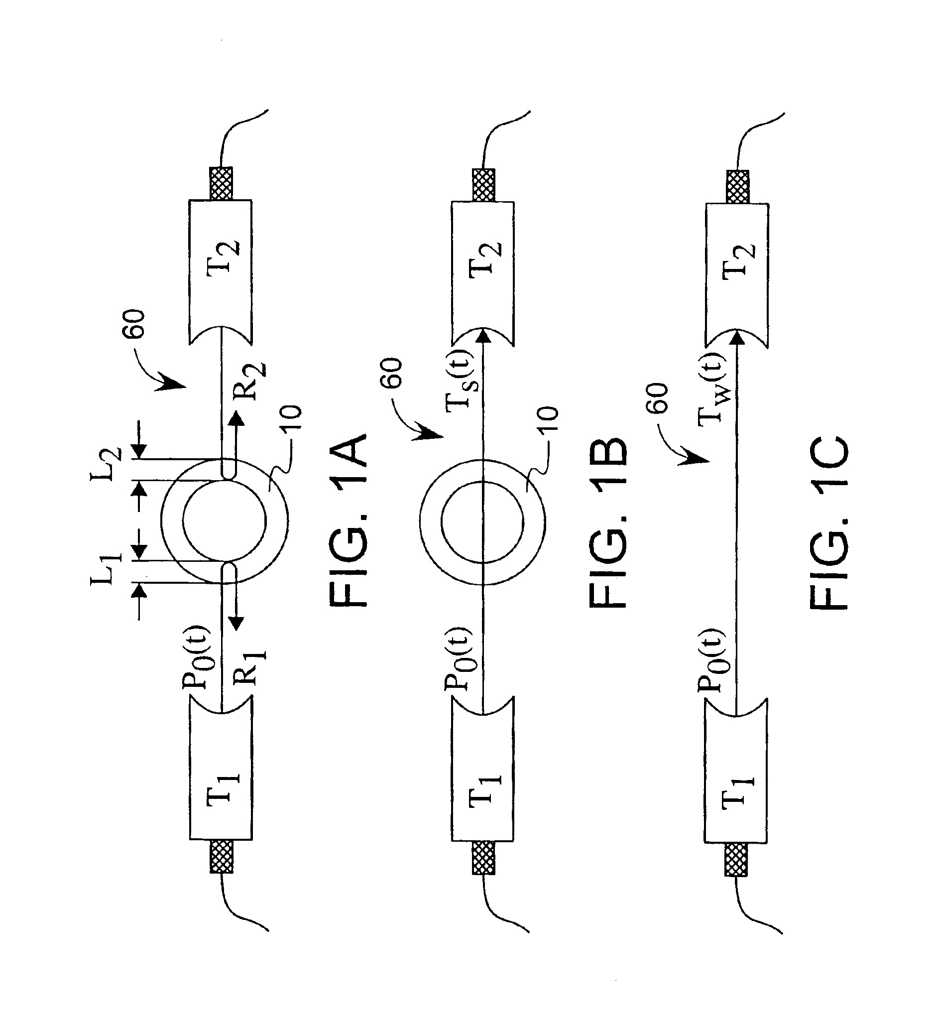
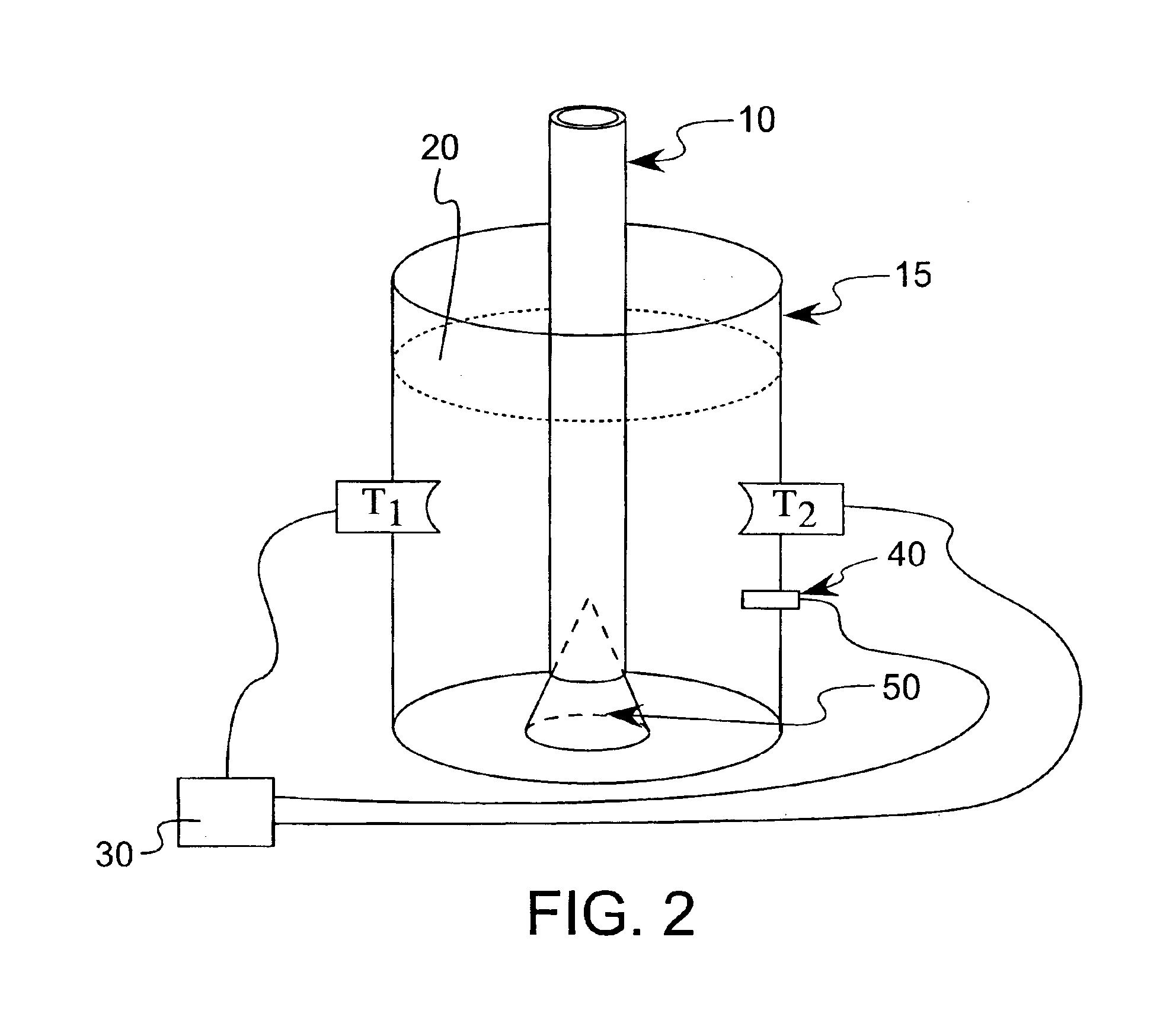
[0026]Referring first to FIGS. 1A through 1C, 2 and 5, a set-up for the use of ultrasonic measurement of a tube is shown. In the present context, the term “measurement” and its variants is understood to include ways of sensing or otherwise detecting a particular quantity, such as time or amplitude of ultrasound signals. In such a context, a measurement is a subset of the larger “determining”, wherein quantities are not only measured, but processed or manipulated (such as by calculation or related computation) to produce a human- or machine-useable output. For example, measured time of flight data may be used to calculate, and thereby determine, speed of sound and thickness values. Referring with particularity to FIG. 2, the set-up includes an object to be measured 10 (in this case, a tube), a measurement chamber 15 (such as a vat), an acoustic couplant medium 20 (typically distilled water), measurement and control electronics 30, a temperature sensor 40, an object positioning device...


PUM


Abstract

A method for the determining ultrasonic sound propagation speed and wall thickness of a tubular object. Time-domain and frequency-domain analyses are used, where the latter can determine acoustic dispersion if the specimen is made up of a dispersive material. Data is sensed from a series of transmitted ultrasonic waves, some of which are reflected. The data can be used to calculate speed of sound in the tube, as well as wall thickness. Inherent in the data is the speed of the ultrasonic wave; accordingly, correction for temperature variations in the tube is not required. The calculations based on measured speed of sound quantities produces more accurate results than in calculations where the speed of sound in the specimen is assumed.

Description

[0001]This application is a continuation in part of U.S. patent application Ser. No. 10 / 055,461, filed Jan. 23, 2002, now U.S. Pat. No. 6,634,233, which claims the benefit of U.S. Provisional Application No. 60 / 263,650 filed Jan. 23, 2001.BACKGROUND OF THE INVENTION[0002]The present invention generally relates to the use of ultrasonic pulses, or waves, to measure the properties of objects in the wave's path, and more particularly to the use of an ultrasonic wave source to determine both the thickness of pipes and tubes and the speed of sound within the same, both from the same set of recorded data and without recourse to assumed or predetermined values of properties unique to the pipe or tube being measured.[0003]Various types of non-destructive measurement methods have been employed in the art for determining an object's structural properties. One method, utilizing ultrasonic waves, is particularly appealing due to its accuracy, relative low cost, and safety. It is commonly used to...

Claims


Application Information

Patent Timeline
IPC IPC(8): G01B17/02G01N29/44G01N29/46G01N29/07G01N29/28G01N29/04
CPCG01B17/02G01N29/07G01N29/28G01N29/46G01N2291/2634G01N2291/02854G01N2291/02881G01N2291/102G01N2291/014
Inventor HE, PING
Owner WRIGHT STATE UNIVERSITY
Why Eureka
Try Eureka