
Dynamic damper

a technology of dynamic dampers and dampers, which is applied in the direction of shock absorbers, machine supports, mechanical equipment, etc., can solve the problems of high total cost including the attachment of dynamic dampers, difficulty in pressing the dynamic damper onto the drive shaft, and impaired durability, so as to ensure the stability of the attachment position and ensure the durability of the support portion members

Inactive Publication Date: 2005-04-26
SUMITOMO RIKO CO LTD
View PDF26 Cites 23 Cited by
  • Summary
  • Abstract
  • Description
  • Claims
  • Application Information

AI Technical Summary

Benefits of technology

[0005]In order to firmly fix the dynamic damper to the drive shaft to prevent axial movement from occurring, the attachment tube of the dynamic damper must be fastened by the fastening band to be pressed against the drive shaft. Therefore, a work of conducting a fastening process by the fastening band is required in a step of attaching the dynamic damper, and the fastening band must be prepared as a separate member, thereby causing a problem in that the total cost including the attachment of the dynamic damper is high. When the degree of interference of press fitting of the attachment tube of the rubber elastic member onto the drive shaft is enhanced, the strength of attachment of the rubber elastic member to the drive shaft is increased. In this case, however, the degree of the compression of the rubber elastic member is very high, and hence the entire rubber elastic member easily collapses, thereby causing the probability that the durability may be impaired. Since the degree of interference of press fitting of the attachment portion onto the drive shaft is very high, there is another problem in that it is very difficult to conduct the work of pressingly fitting the dynamic damper onto the drive shaft.
[0006]The invention has been conducted in order to solve the above-discussed problems. It is an object of the invention to provide a dynamic damper which can be firmly fixed to a rotary shaft without using a fastening band, and in which the durability of a rubber elastic member can be adequately ensured, and the work of attachment to the rotary shaft is facilitated.
[0007]In order to attain the problems, the invention provides a dynamic damper for damping vibration of a rotary shaft, including: a tubular mass member; and a rubber elastic member that elastically supports the mass member on the rotary shaft, the rubber elastic member including an attachment tube and an arm both made of a rubber elastic material, the attachment tube disposed coaxially with the mass member but nearer to an axial center thereof than the mass member, the attachment tube to be press-fitted onto an outer peripheral face of the rotary shaft, the arm connecting the attachment tube to the mass member. The attachment tube includes: a tubular support portion including a part connected to the arm; a tubular attachment portion; and a tubular coupling portion for coupling the tubular support portion with the tubular attachment portion. The tubular attachment portion has larger interference than the tubular support portion where the interference is a value obtained by dividing a difference between an inner diameter before press fitting onto the rotary shaft and an outer diameter of the rotary shaft by the inner diameter before press fitting. Preferably, the tubular coupling portion is formed to prevent the tubular support portion from being affected by deformation of the tubular attachment portion due to press-fitting onto the rotary shaft.
[0008]According to this, the dynamic damper is fixed to the rotary shaft in which vibrations are to be damped, by pressingly fitting the attachment tube of the rubber elastic member onto the outer peripheral face of the rotary shaft, thereby allowing the mass member to be elastically supported by the rubber elastic member with respect to the rotary shaft. Since the degree of interference of the attachment portion of the attachment tube is larger than that of the support portion, the rubber elastic member is firmly fixed to the rotary shaft, mainly by the attachment portion. Even when a fastening band is not used, therefore, axial movement of the dynamic damper due to a vibration input from the rotary shaft is suppressed, and the attachment position is stably ensured. Since the degree of interference of the support portion of the attachment tube with which the arm is coupled to directly support the mass member is smaller than that of the attachment portion, collapse of the rubber elastic material is suppressed, and the durability is ensured. Furthermore, the coupling portion is disposed between the support portion and the attachment portion of the larger degree of interference, so that the support portion is prevented from being affected by compression deformation of the rubber elastic material in the attachment portion which is fitted by pressing onto the rotary shaft. In the dynamic damper, therefore, the support portion is uniformly fixed to the rotary shaft, and hence the vibration damping performance of the dynamic damper can be adequately maintained. In the rubber elastic member, the portion of a larger degree of interference is restricted to the attachment portion. In the entire rubber elastic member, therefore, also difficulty of the work of pressingly fitting onto the rotary shaft can be reduced.
[0011]The terms “buffer length” means the length of the coupling portion which is required for preventing the support portion from being affected by deformation of the attachment portion due to press fitting onto the rotary shaft. Since the coupling portion is thinner than the support portion and the attachment portion, or has a predetermined buffer length in the axial direction, large deformation of the rubber elastic material due to press fitting of the attachment portion of a larger degree of interference onto the rotary shaft is absorbed by the thinned part or the buffer length, and hence does not affect even the support portion. Therefore, the support portion can be uniformly fixed to the rotary shaft, so that the vibration damping performance of the rubber elastic member can be adequately maintained.
[0014]When the degree of interference of the support portion is in the range of 5 to 20% as described above, collapse of the support portion is suppressed, and the durability of the support portion member is ensured. When the degree of interference of the attachment portion is set to 20 to 50%, the strength of attachment of the attachment portion to the rotary shaft is sufficiently ensured, axial movement of the dynamic damper with respect to the drive shaft is suppressed, and the attachment position is stably ensured.

Problems solved by technology

Therefore, a work of conducting a fastening process by the fastening band is required in a step of attaching the dynamic damper, and the fastening band must be prepared as a separate member, thereby causing a problem in that the total cost including the attachment of the dynamic damper is high.
In this case, however, the degree of the compression of the rubber elastic member is very high, and hence the entire rubber elastic member easily collapses, thereby causing the probability that the durability may be impaired.
Since the degree of interference of press fitting of the attachment portion onto the drive shaft is very high, there is another problem in that it is very difficult to conduct the work of pressingly fitting the dynamic damper onto the drive shaft.

Method used


Image

  • Dynamic damper
  • Dynamic damper
  • Dynamic damper

Examples


first embodiment

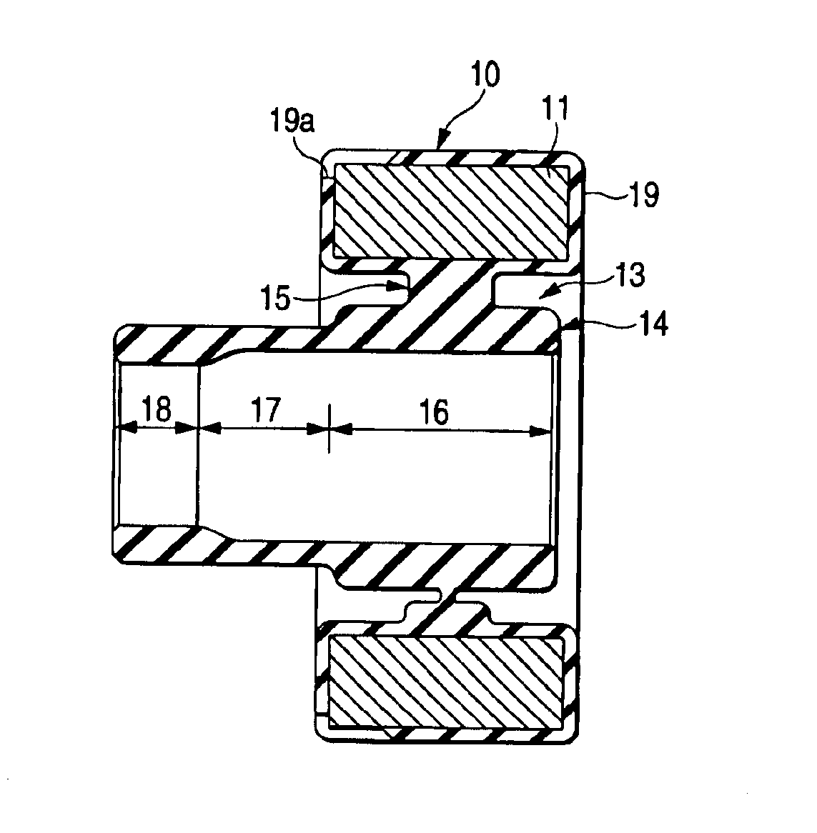
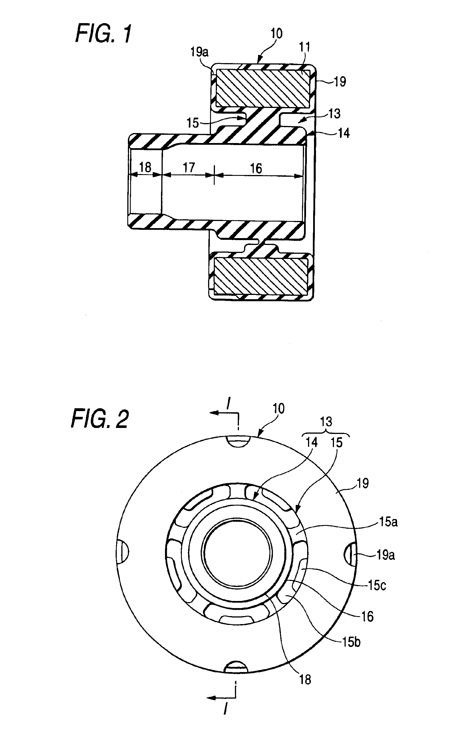
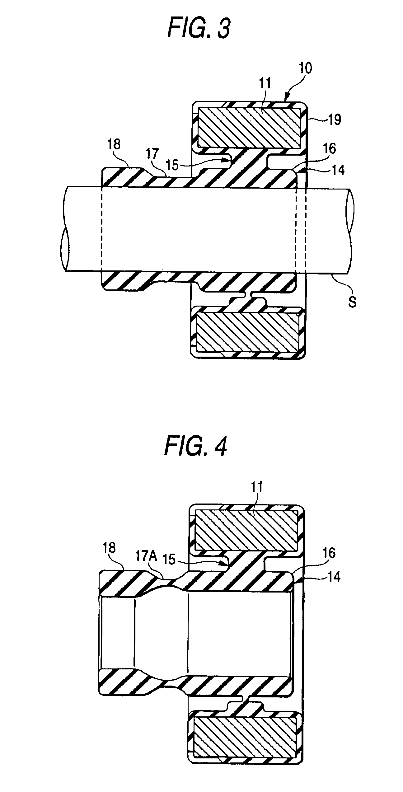
[0029]Hereinafter, an embodiment of the invention will be described with reference to the accompanying drawings. FIGS. 1 and 2 are a section view taken along the line I—I and a left side view showing a dynamic damper 10 which is a first embodiment, and which is to be attached to a drive shaft (rotary shaft) S of an automobile. FIG. 3 is a section view taken along the axis showing a state where the dynamic damper 10 is fitted by pressing onto the drive shaft S.

[0030]The dynamic damper 10 includes: a cylindrical metallic mass (tubular mass member) 11; a rubber elastic member 13 which extends from the inner peripheral face of the metallic mass 11 toward the axial center; and a rubber covering layer 19 which covers the surface of the metallic mass 11. The rubber elastic member 13 and the rubber covering layer 19 are formed integrally with the metallic mass 11 by the vulcanization and molding method and in an unbonded manner. The rubber elastic member 13 is configured by: a cylindrical a...

second embodiment

[0047]Next, a second embodiment will be described with reference to the accompanying drawings. FIGS. 6 and 7 are a section view taken along the line VI—VI and a left side view showing a dynamic damper of the embodiment. The dynamic damper 20 comprises: a cylindrical metallic mass 21; first and second tubular attachment tubes 22 and 23 which are made of a rubber elastic material, and which are coaxially disposed on axially outer sides of the right and left ends of the metallic mass with being separated therefrom by a predetermined distance, respectively; a pair of tubular arms 26, 27 which are made of a rubber elastic material, and which connect the ends of the metallic mass 21 to the first and second attachment tubes 22 and 23 over the whole circumference, respectively; and thin rubber covering layers 28a and 28b which cover the inner and outer peripheral faces of the metallic mass 21, respectively. The first attachment tube 22 and the arm 26, and the second attachment tube 23 and t...


PUM


Abstract

A dynamic damper for damping vibration of a rotary shaft. The dynamic damper includes a tubular mass member and a rubber elastic member. The rubber elastic member includes an attachment tube press-fitted onto the rotary shaft and an arm. The attachment tube is disposed coaxially with the mass member but nearer to an axial center thereof than the mass member. The arm connects the attachment tube to the mass member. The attachment tube includes a tubular support portion connected to the arm, a tubular attachment portion, and a tubular coupling portion for coupling the tubular support portion with the tubular attachment portion. The tubular attachment portion has larger interference than the tubular support portion.

Description

BACKGROUND OF THE INVENTION[0001]1. Field of the Invention[0002]The present invention relates to a dynamic damper which is to be fitted onto an outer peripheral face of a rotary shaft such as a drive shaft of a vehicle, and which damps a vibration input produced on the rotary shaft.[0003]2. Background Art[0004]Conventionally, a dynamic damper of this kind comprises, for example, a tubular metallic mass, and a tubular rubber elastic member which extends from the inner peripheral face of the metallic mass toward the axial center. The rubber elastic member has an attachment tube which is placed on the side of the axial center, and an arm which couples the attachment tube with the metallic mass. The attachment tube is fitted by pressing onto an outer peripheral face of a rotary shaft such as a drive shaft in which vibrations are to be damped, whereby the metallic mass is elastically held onto the drive shaft. In the dynamic damper, in response to a harmful vibration input such as bendin...

Claims


Application Information

Patent Timeline
IPC IPC(8): F16F15/10F16F15/14F16F15/126
CPCF16F15/1442Y10T464/50F16F15/10
Inventor KATO, KAZUHIKOASANO, SEIYASUGIURA, TAKANORI
Owner SUMITOMO RIKO CO LTD
Learn More