Three dimensional vector cardiograph and method for detecting and monitoring ischemic events

a three-dimensional vector and cardiac muscle technology, applied in the field of three-dimensional vector cardiograph and method for detecting and monitoring ischemic events, can solve the problems of high system redundancy, difficult to determine the net vector effect of this 3-d wave and its relationship to the overall movement of the cardiac muscle, and other techniques such as two-dimensional (2-d) vector cardiograms have proved in the past to be quite expensive and cumbersome, so as to enhance diagnostic analysis, enhance analysis and heart monitoring techniques, and enhance recognition

Inactive Publication Date: 2005-04-26
ECG TECH CORP
View PDF29 Cites 72 Cited by
  • Summary
  • Abstract
  • Description
  • Claims
  • Application Information

AI Technical Summary

Benefits of technology

[0036]It is also an object of the present invention to provide a device which interprets the sampled data from an ECG digitally recorded signal at certain time intervals and projects this signal as a vector from a point of origin to a point in 3-D space as related to the X, Y and Z axes. Such display information can include various intervals and critical parameters relating to the ECG signal, e.g., P-wave, QRS interval including the initiation and end points of the QRS interval, ST segment, J point, T wave, etc. In addition, other information relating to the magnitude of the vector differences and the angle (elevational and azimuth values) may also be displayed relating to two ECG signal taken over a period of time. It is envisioned that measuring, calculating and displaying this information may lead to better analysis and heart monitoring techniques.
[0037]The present disclosure also eliminates the step-by-step analytical process of determining heart conditions and ischemic events and provides a new techniques and new displays which are intended to enhance recognition of the presence and type of malfunctions related to the cardiac muscle.
[0038]As mentioned above, it is envisioned that the display can integrate other information about the heart onto the same display which it is believed will further enhance diagnostic analysis, e.g., a calibrated display of the magnitude of the vector (Magnitude=squareroot (X2+Y2+Z2)) for easier evaluation of hypertrophy and possibly other conditions; displaying the change in Magnitude from one vector to the next, which is believed to be an indication of the continuity of heart muscle cell activation and an additional indicator of disease; and displaying the change in the angle of the heart vectors over the same time interval which is believed to be a further indicator of muscle cell activation and smoothness of transition of the depolarization of cells over the myocardium.
[0039]By visually projecting the results of the 3-D heart vectors (and accompanying information relating thereto) onto three planes, namely, the frontal, the transverse and the sagittal planes, heart analysis is greatly simplified and further enhanced. The display is preferably color-coded to distinguish the vector sequence over the QRS cycle, e.g., by color coding the time of occurrence of the events in the QRS cycle, the ST offset, and the T-wave to clearly show their inter-relationship and timing which is important to the recognition of normal versus diseased conditions.
[0040]Further embodiments of the display allow a physician or medical technician to manipulate the vector display to facilitate more detailed examination of any portion of the vector sequence as a function of time, e.g., the vector display may be expanded or magnified to highlight and allow closer examination of certain areas; the vector display may be shifted in steps both horizontally and vertically from its present location; the vector display may be rotated about the vertical axis 360 degrees, and elevated or declined about the X-axis in steps; and the T-wave, P-wave or other portion of the display may be removed if it interferes with the observation of other portions of the signal.

Problems solved by technology

Other techniques such as two-dimensional (2-D) vector cardiograms have proven in the past to be quite expensive and cumbersome due to the relative cost and size of the equipment needed to properly display the vector cardiograms, e.g., one cathode ray tube (CRT) oscilloscope was needed for the display of each bodily plane.
Early experimental work showed the timing of this excitation and the progress of the electrical wave through the right and left ventricles of the heart, however, it was very difficult to determine the net vector effect of this 3-D wave and its relationship to the overall movement of the cardiac muscle.
This system is highly redundant.
As can be appreciated from the above summary, the analytical process of determining the resultant QRS vector and the other vectors can be quite cumbersome and requires a physician to interpret various graphs and / or solve various formulas which tend only to frustrate the diagnostic process and which can lead to erroneous conclusions if analyzed improperly.
However, as often is the case, the determination of the mean vectors (QRS, T and P) in one plane is still both time consuming and somewhat confusing.
Further, trying to determine how the mean vectors project into two planes and how the angles between the vectors relate can be even more confusing.
Moreover, even if a physician can adequately analyze the various graphs and solve the various formulas to arrive at a diagnosis, three-dimensional representation of the location of the mean QRS vectors (and the other vectors) must be mentally visualized which requires a high degree of mental agility and can lead to misdiagnosis.
Further, mentally visualizing the angles between mean vectors would be virtually impossible for even the most skilled physician.
The additional problem of how these vectors change in time over the QRS interval is believed to be nearly impossible to consider by the prior methods.
However, as far as is known no one has ever attempted to display the signal as a series of 3-D vectors plotted at intermittent time intervals over the duration of the signal, much less represent these vectors on a single display and on a single 3-D coordinate system thereby producing a more easily identifiable 3-D view of the 12-Lead ECG signal or QRS complex as it progresses through the cardiac muscle over time.
For example and as mentioned above, continual heart monitoring utilizing a standard 12-lead display system is a demanding process.
As is often the case, false signals are generated which, as can be appreciated, can be a tremendous waste of hospital resources.
As can be appreciated, this can be stressful on the hospital staff.

Method used


Image

  • Three dimensional vector cardiograph and method for detecting and monitoring ischemic events
  • Three dimensional vector cardiograph and method for detecting and monitoring ischemic events
  • Three dimensional vector cardiograph and method for detecting and monitoring ischemic events

Examples


Embodiment Construction

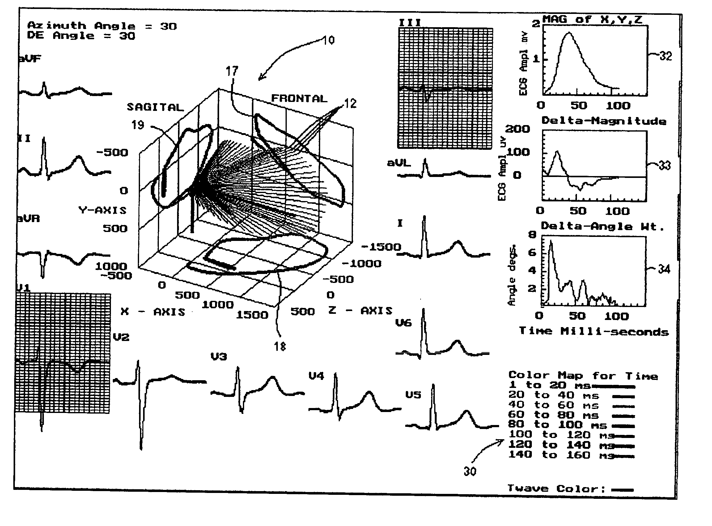
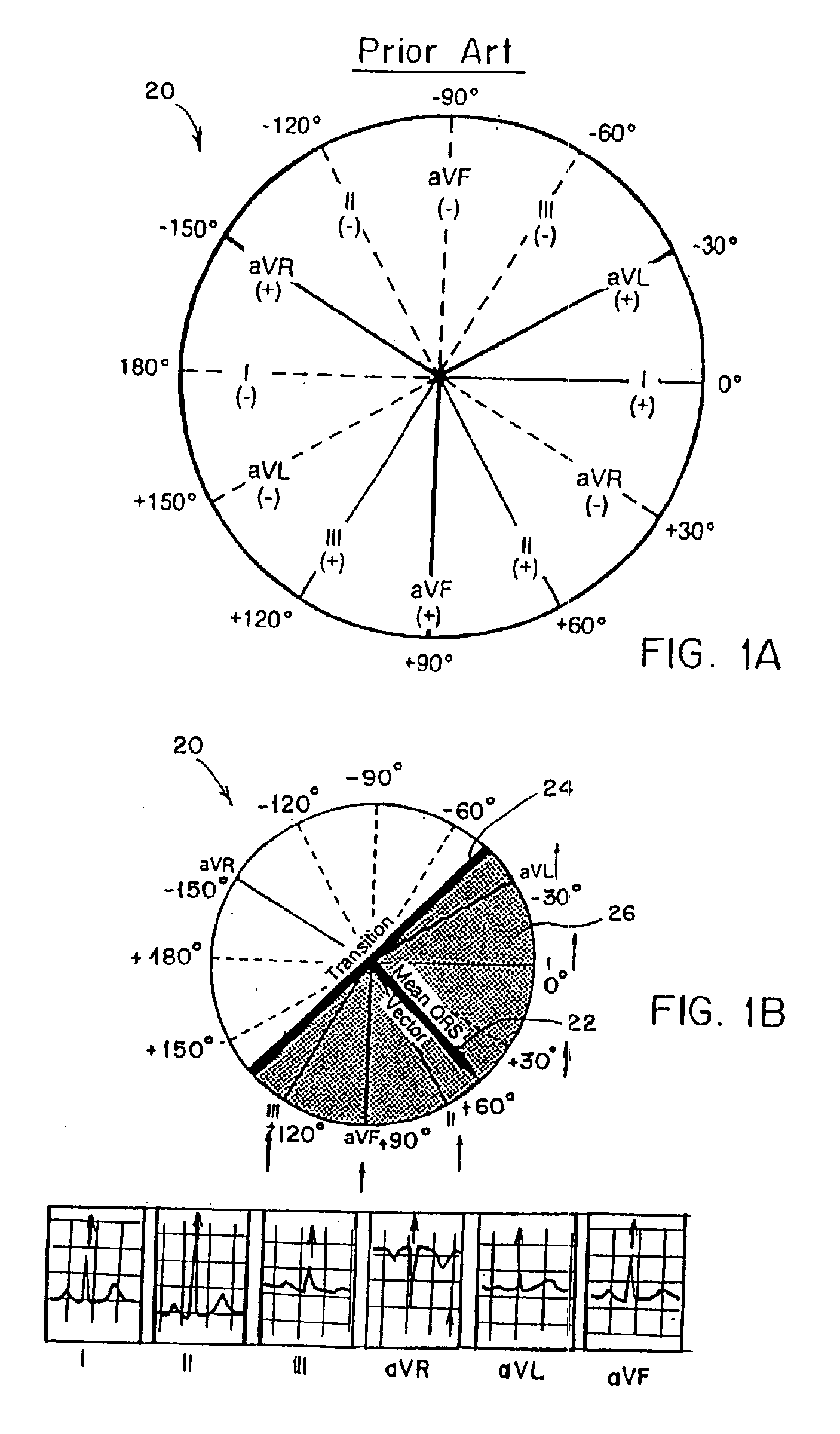
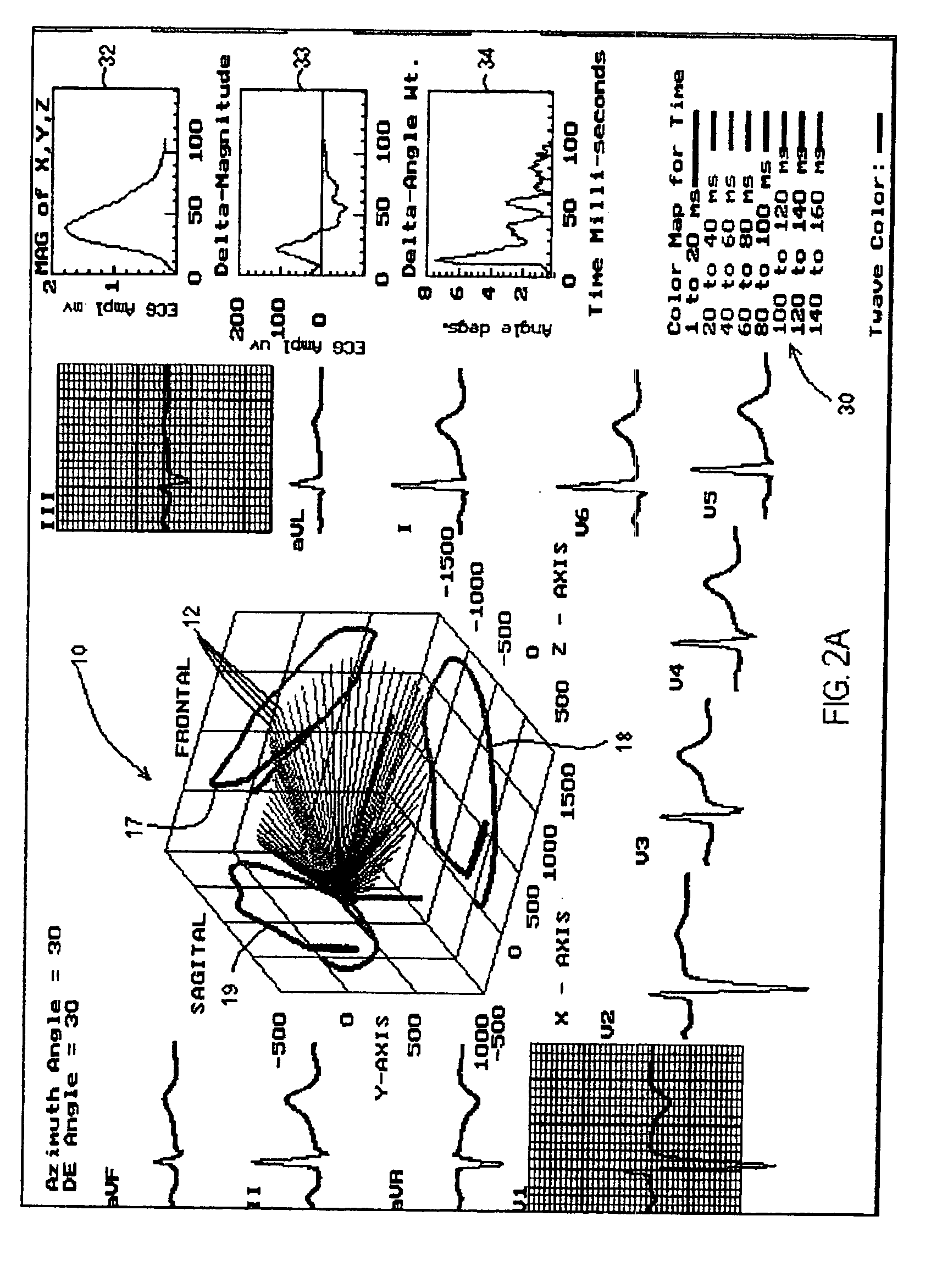
[0079]Conventional cardiographs display electrocardiograph heart signals in vector format within a conventional coordinate system comprising the “x” and “y” axes. The present disclosure relates to a vector cardiograph coordinate system sampled at incremental time intervals which comprises a point of origin and a three-dimensional coordinate system comprising an x-axis, a y-axis and a z-axis extending from the point of origin. As defined, the three dimensional coordinate system includes a frontal plane defined by the area between the x-axis and the y-axis, a sagittal plane defined by the area between the z-axis and the y-axis and a transverse plane defined by the area between the x-axis and the z-axis. One such system is described in commonly-owned U.S. Pat. No. 5,803,084 the entire contents of which is incorporated herein in its entirety. The '084 patent discloses a displaying mechanism which displays the magnitude and location of the signal within a three dimensional coordinate sys...


PUM


Abstract

A method of determining an ischemic event includes the steps of: monitoring and storing an initial electrocardiogram vector signal (x, y, z) of a known non-ischemic condition over the QRS, ST and T wave intervals; calculating and storing a J-point of the vector signal and a maximum magnitude of a signal level over the T wave interval; monitoring a subsequent electrocardiogram vector signal over the QRS, ST and T wave intervals; measuring and storing the magnitude (Mag.) of the vector difference between a subsequent vector signal and the initial vector signal; measuring and storing the angle (Ang.) difference between a subsequent vector and the initial vector at points; regressing a line from points about 25 milliseconds prior to the J point and about 60 milliseconds after the J-point and determining the slope of the regression line and the deviation of the angle difference of the regression line; regressing a line from points about 100 milliseconds prior to the maximum magnitude of the signal level over the T wave interval and determining the slope of the regressing line and the deviation of the angle difference of the regression line; and comparing the slope and deviation of the lines from the J point and the T wave interval to a set of known values to determine the presence of an ischemic event.

Description

CROSS REFERENCE TO RELATED APPLICATION[0001]The present application claims the benefits of and priority to U.S. Provisional Patent Application Ser. No. 60 / 431,862 filed on Dec. 9, 2002, the entire contents of which are incorporated herein by reference.BACKGROUND[0002]The present disclosure relates to a method for detecting and monitoring electrical signals from the heart for analysis of heart malfunctions. More particularly, the presently disclosed method relates to a technique for distinguishing between ischemic electrocardiograph (ECG) events and patient positional changes during patient monitoring.[0003]Multi-lead ECGs for diagnosing various heart maladies have been used for many years. The most prevalent technique for analyzing and diagnosing heart conditions involves a 12-lead system. The 12-Lead system provides much redundant information in the frontal plane (X, Y) and transverse plane (X, Z) of the ECG vector signal. It permits only a rough visual estimate of the vector direc...

Claims


Application Information

Patent Timeline
Patent Type & Authority Patents(United States)
IPC IPC(8): A61B5/0472A61B5/04A61B5/0452A61B5/366
CPCA61B5/04011A61B5/0472A61B5/7239A61B5/341A61B5/366
Inventor OLSON, CHARLES W.
Owner ECG TECH CORP
Why Eureka
Try Eureka