Ni-based sintered alloy

a sintered alloy and ni-based technology, applied in the direction of engines, mechanical equipment, machines/engines, etc., can solve the problems of insufficient sintering and inability to obtain sufficient mechanical strength, and achieve the effect of overcoming mechanical strength deficiency and avoiding welding defects

Inactive Publication Date: 2005-04-26
MITSUBISHI HITACHIPOWER SYST LTD
View PDF12 Cites 19 Cited by
  • Summary
  • Abstract
  • Description
  • Claims
  • Application Information

AI Technical Summary

Benefits of technology

[0009]An object of the present invention is to provide a Ni-based sintered alloy, by mixing and heating two kinds of Ni alloy powders of different melting points, so as to render welding unnecessary and, thus, to avoid the generation of welding defects caused by welding, and overcome the deficiency in mechanical strength.
[0011]In this case, a high melting point Ni alloy powder having a melting point higher than the heating temperature in the sintering treatment and a low melting point Ni alloy powder having a melting point lower than the heating temperature in the sintering treatment are used as the two kinds of the Ni alloy powders, in a preferred embodiment, for example, so as to permit the low melting point Ni alloy powder alone to be melted during the heating for the sintering treatment, thereby allowing the molten low melting point Ni alloy powder to fill the clearances among the high melting point Ni alloy powder particles and achieving a mutual diffusion. In other words, the low melting point Ni alloy powder is mixed with the high melting point Ni alloy powder so as to make it possible to obtain a Ni-based sintered alloy having a high mechanical strength.
[0013]Also, in another embodiment it is desirable to set the compositions of the high melting point Ni alloy powder and the low melting point Ni alloy powder such that the composition of the Ni-based sintered alloy formed after the sintering treatment is rendered substantially equal to the composition of the Ni alloy used as the base material of the high temperature part. If the Ni-based sintered alloy formed after the sintering treatment is rendered substantially equal in composition to the base material of the high temperature part, the Ni-based sintered alloy is rendered compatible with the base material of the high temperature part in the interface between the Ni-based sintered alloy and the base material of the high temperature part so as to make it possible to increase the coupling strength between the two.
[0029]According to the present invention, the Ni-based sintered alloy is prepared by mixing and heating two kinds of Ni alloy powders differing from each other in the melting point so as to make it unnecessary to employ the welding treatment. It follows that the present invention makes it possible to provide a Ni-based sintered alloy that permits avoiding the occurrence of welding defects caused by the welding treatment and also permits overcoming the insufficient mechanical strength. Also, it is possible to render the composition of the formed Ni-based sintered alloy substantially equal to the composition of the base material of the high temperature part. It follows that the base material is rendered compatible with the Ni-based sintered alloy at the interface between the two so as to make it possible to overcome the insufficient coupling strength after the repair.

Problems solved by technology

If the mixing ratio of the low melting point Ni alloy powder is lower than 30% by weight, the low melting point Ni alloy powder fails to be diffused sufficiently, with the result that the sintering does not proceed sufficiently.
It follows that a sufficiently high mechanical strength cannot be obtained.

Method used


Image

  • Ni-based sintered alloy
  • Ni-based sintered alloy

Examples


example 1

[0043]In this Example, the bulk molding will be described with reference to FIG. 2. First of all, the two kinds of Ni alloy powders forming the Ni-based sintered alloy powder are formed of the powders having the compositions given below:[0044]Low melting point Ni alloy powder: Ni-10.7 Cr-17.2 Co-2.6 Mo-2.0 W-5.8 Ta-8.6 Ti-8.7 Al-2.6 Nb-1.2 B-0.27Zr[0045]High melting point Ni alloy powder: Ni-17.1 Cr-3.1 W-0.19C

[0046]A Ni-based sintered alloy powder was prepared by mixing in, for example, a ball mill, 45% by weight of the low melting point Ni alloy powder of the composition given above and 55% by weight of the high melting point Ni alloy powder of the composition given above. After the Ni-based sintered alloy powder was subjected to a compression molding in the shape of a vane, the molded powder was sintered by the heating at 1,215° C. for 8 hours. Then, a stepwise heat treatment including the heating at 1,120° C. for 2 hours and the additional heating at 850° C. for 24 hours, which ...

example 2

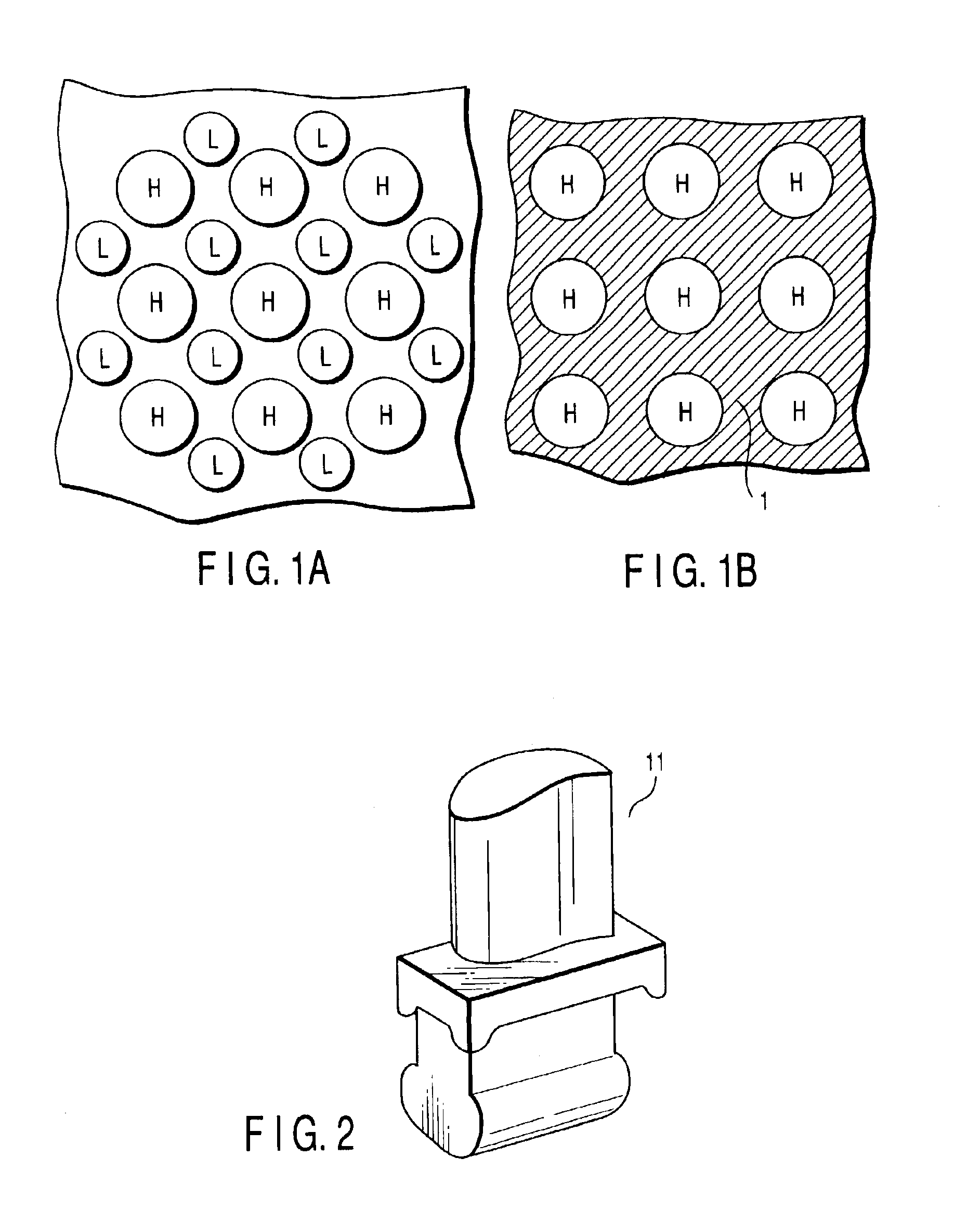
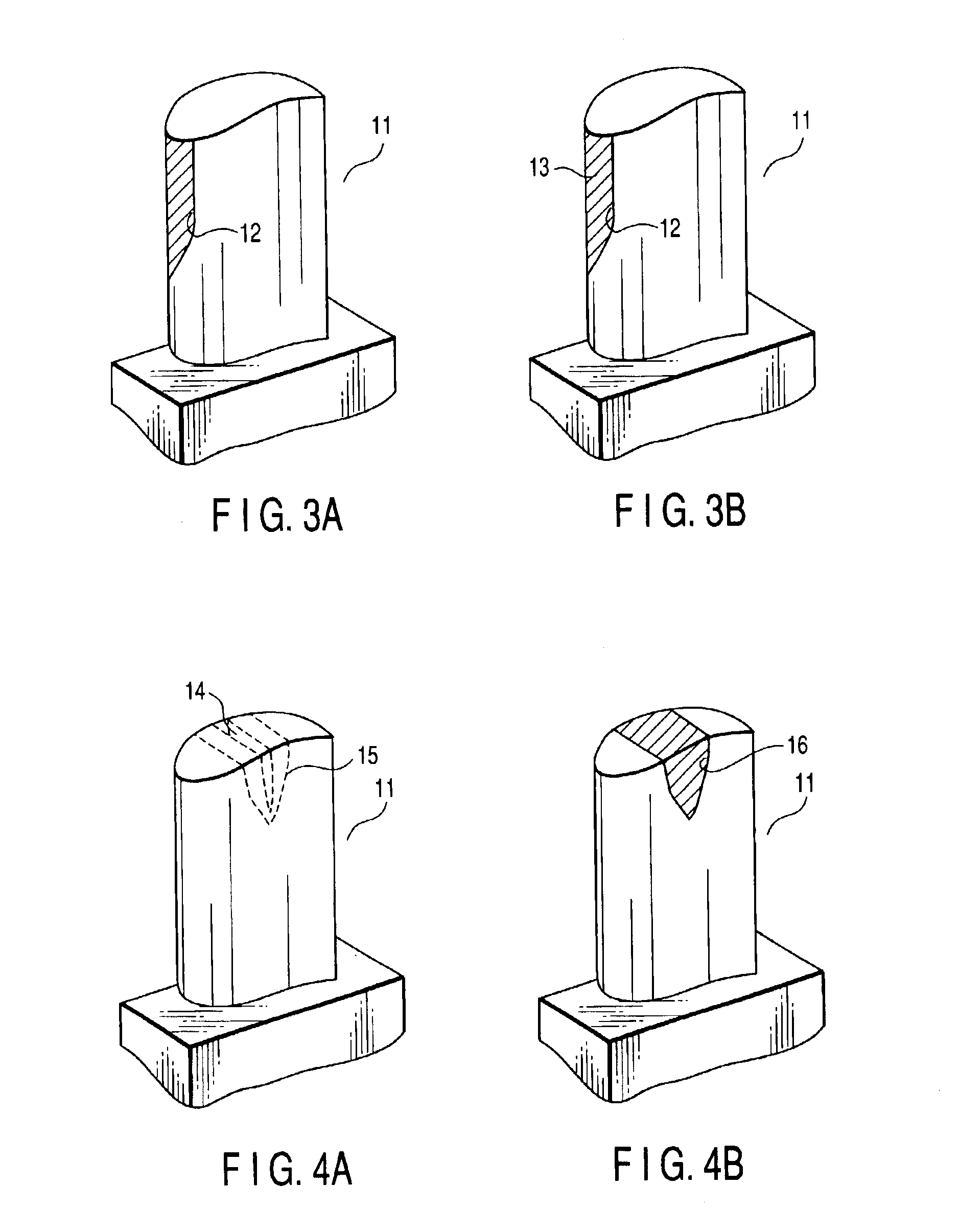
[0049]In this Example, the coating will be described with reference to FIGS. 3A and 3B. FIG. 3A schematically shows the construction of a dynamic vane before the coating, and FIG. 3B schematically shows the dynamic vane after the coating. The Ni-based sintered alloy powder used in Example 2, which included a low melting point Ni alloy powder and a high melting point Ni alloy powder, was equal in composition to the Ni-based sintered alloy powder used in Example 1.

[0050]To be more specific, a Ni-based sintered alloy powder was prepared by mixing, in a ball mill, 45% by weight of a low melting point Ni alloy powder having a particle diameter not larger than 75 μm and 55% by weight of a high melting point Ni alloy powder having a particle diameter not larger than 150 μm. Then, the Ni-based sintered alloy powder was blown onto a thin portion 12 of the dynamic vane 11 shown in FIG. 3A by, for example, a low pressure plasma spraying method so as to achieve the coating, followed by heating ...

example 3

[0052]In this Example, a local padding will be described with reference to FIGS. 4A and 4B. FIG. 4A schematically shows the dynamic vane before the local padding treatment, and FIG. 4B schematically shows the dynamic vane after the local padding treatment. Also, the Ni-based sintered alloy powder used in Example 3, which included a low melting point Ni alloy powder and a high melting point Ni alloy powder, was equal in composition to the Ni-based sintered alloy powder used in Example 1.

[0053]Example 3 covers the case of repairing, for example, a cracked portion 14 of the dynamic vane 11. In the case of Example 3, a peripheral portion 15 of the cracked portion 14 denoted by dotted lines in FIG. 4A is removed first by the cutting with, for example, a grinder. Then, a Ni-based sintered alloy powder is prepared by mixing, in a ball mill, 45% by weight of a low melting point Ni alloy powder and 55% by weight of a high melting point Ni alloy powder, followed by kneading the resultant Ni-b...


PUM

PropertyMeasurementUnit
melting pointaaaaaaaaaa

Abstract

Disclosed is a Ni-based sintered alloy used for preparing a high temperature part utilized under a high temperature gas atmosphere, characterized in that the Ni-based sintered alloy is prepared by mixing and heating two kinds of Ni alloy powders differing from each other in the melting point.

Description

CROSS-REFERENCE TO RELATED APPLICATIONS[0001]This is a Continuation Application of PCT Application No. PCT / JP02 / 07433, filed Jul. 23, 2002, which was not published under PCT Article 21(2) in English.[0002]This application is based upon and claims the benefit of priority from the prior Japanese Patent Applications No. 2001-223344, filed Jul. 24, 2001; and No. 2002-195451, filed Jul. 4, 2002, the entire contents of both of which are incorporated herein by reference.BACKGROUND OF THE INVENTION[0003]1. Field of the Invention[0004]The present invention relates to a Ni-based sintered alloy, used for forming high temperature parts in gas turbines, jet engines, etc., particularly, for forming a dynamic vane or a static vane.[0005]2. Description of the Related Art[0006]It is known to the art that a cast alloy or a forged alloy is generally used for forming dynamic and static vanes used under high temperature atmospheres, such as in a gas turbine or jet engine. However, these alloys are insuf...

Claims


Application Information

Patent Timeline
Patent Type & Authority Patents(United States)
IPC IPC(8): B22F1/00C22C1/04F01D5/28C22C19/05F02C7/00
CPCB22F1/0003B23P6/002C22C1/0433B22F3/1035B22F2998/00B22F2999/00B22F1/00
Inventor OKADA, IKUOOHSAWA, KEIOGUMA, HIDETAKATAKAHASHI, KOJIONDA, MASAHIKOSETO, TAKESHI
Owner MITSUBISHI HITACHIPOWER SYST LTD
Why Eureka
Try Eureka