Method for removing volatile components from a high viscosity liquid by using rotation pack bed
a technology of high viscosity liquid and volatile components, which is applied in the direction of liquid degasification, separation process, filtration separation, etc., can solve the problems of increasing energy consumption, not being able to accept continuous feeds in the tank, and requiring more than 10-hours processing for the retention time of a batch of 4 tons, so as to achieve high viscosity and high viscosity. , the effect of high viscosity
- Summary
- Abstract
- Description
- Claims
- Application Information
AI Technical Summary
Benefits of technology
Problems solved by technology
Method used
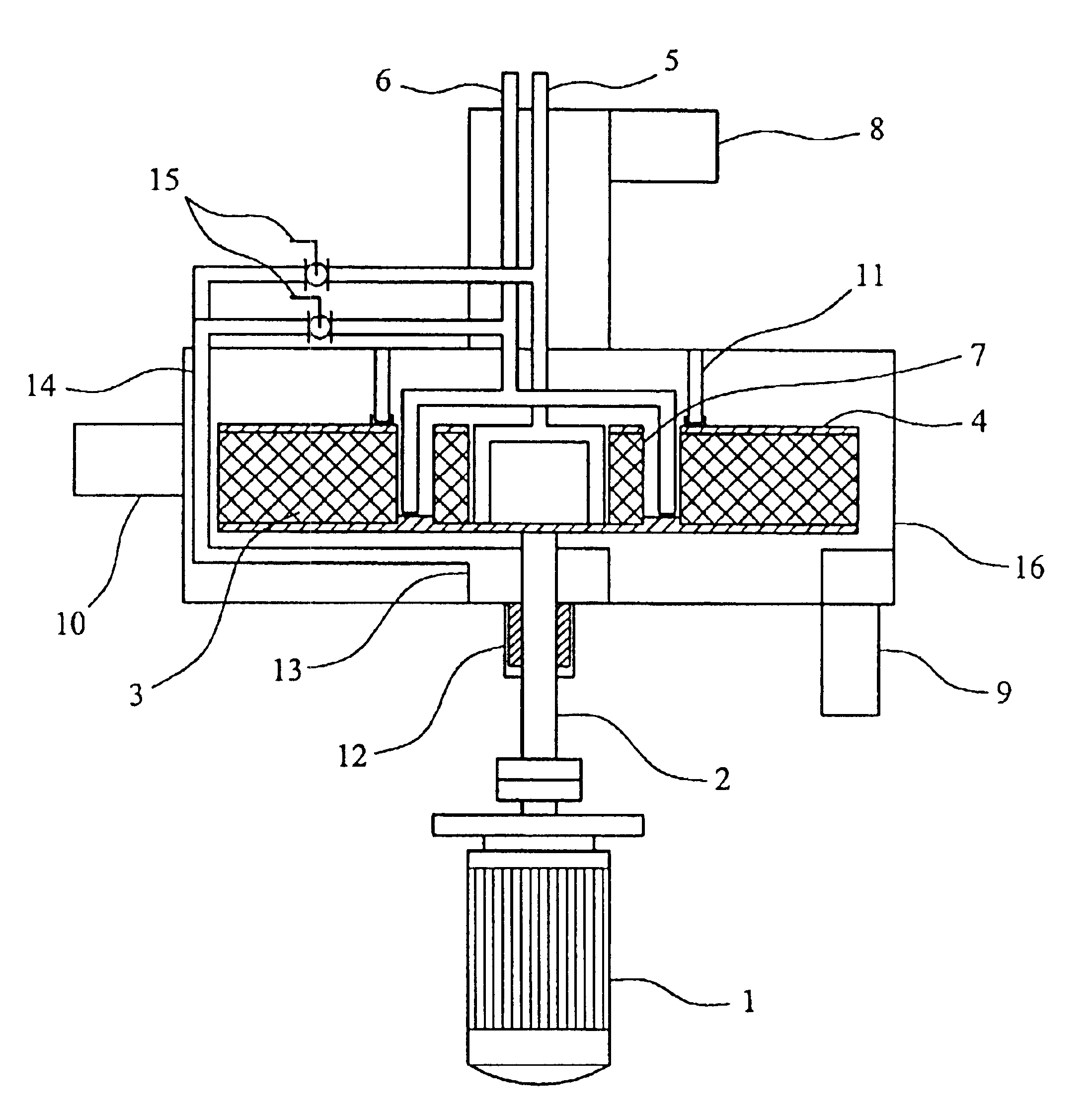
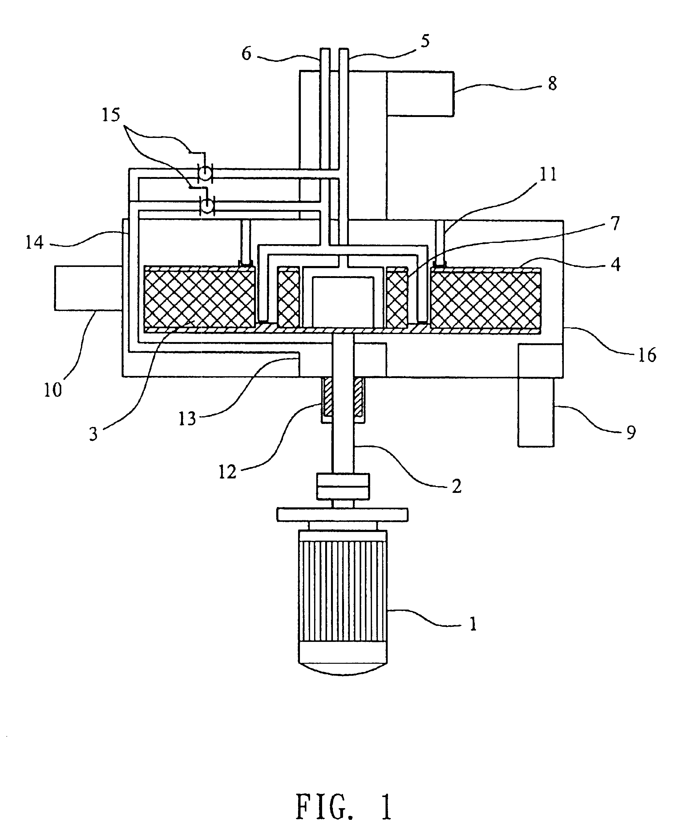
Image

Examples
examples 1-3
Batchwise Removal of HCl from TNPP (Tris Nonylphenol Phosphite)
[0043]The specifications of the pack bed used in these examples were: inside diameter 76 mm, outside diameter 160 mm, and thickness 33 mm. The rotation speed of the pack bed was fixed at 1300 rpm, and nitrogen was used as a carrying agent. The inlet position of TNPP was at a location 35 mm from the axis of the pack bed. 5 kg of TNPP (having an acid value of 0.18 mgKOH / g, and a viscosity of 1000 cps) was taken. The temperature of TNPP feed and the gas / liquid ratio of nitrogen to TNPP were altered as shown in Table 1. The results were also shown in Table 1. The test results indicated that the acid value of TNPP, after 15 minutes of processing (one cycle) by the rotation pack bed, was reduced to 0.06˜0.08 mgKOH / g. After a consecutive treatment to 45 minutes (three cycles in total), the acid value of TNPP dropped to 0.04˜0.06 mgKOH / g.
[0044]
TABLE 1Example123Acid value of feedmg KOH / g0.180.180.18Acid value of dischargemg KOH / g...
example 4
Continuous Removal of HCl from TNPP
[0045]The specifications of the pack bed used in this example were: inside diameter 120 mm, outside diameter 600 mm, and thickness 100 mm. The rotation speed of the pack bed was fixed at 1200 rpm. The inlet of the TNPP feed was at a location 50 mm from the axis of the pack bed. The nitrogen temperature was 88° C., and the flow rate of nitrogen was 1250 l / min. The viscosity of TNPP was 1000 cps, the temperature of TNPP was 114° C., and the flow rate of TNPP was 25 l / min. Prior to the processing by the pack bed, the acid value of TNPP was 0.3 mgKOH / g; and the acid value decreased to 0.16 mgKOH / g after being processed.
PUM
| Property | Measurement | Unit |
|---|---|---|
| acid value | aaaaa | aaaaa |
| thickness | aaaaa | aaaaa |
| thickness | aaaaa | aaaaa |
Abstract
Description
Claims
Application Information
 - R&D
- Intellectual Property
- Life Sciences
- Materials
- Tech Scout
- Unparalleled Data Quality
- Higher Quality Content
- 60% Fewer Hallucinations
Browse by: Latest US Patents, China's latest patents, Technical Efficacy Thesaurus, Application Domain, Technology Topic, Popular Technical Reports.
© 2025 PatSnap. All rights reserved.Legal|Privacy policy|Modern Slavery Act Transparency Statement|Sitemap|About US| Contact US: help@patsnap.com