Minimally spaced MRAM structures

Inactive Publication Date: 2005-04-26
OVONYX MEMORY TECH LLC
View PDF19 Cites 0 Cited by
  • Summary
  • Abstract
  • Description
  • Claims
  • Application Information

AI Technical Summary

Benefits of technology

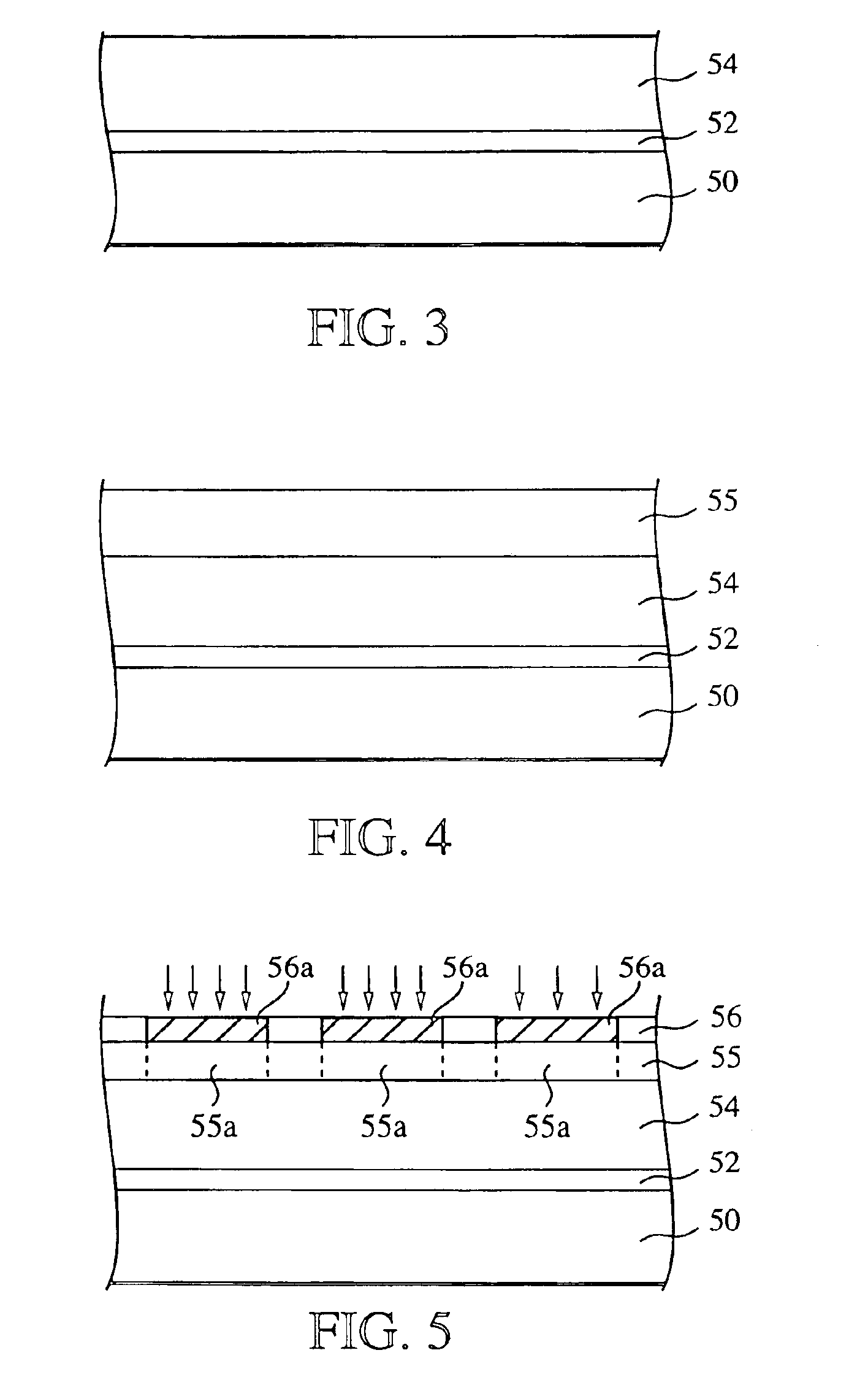
[0010]The present invention provides a method for forming minimally spaced MRAM structures, such as pinned layers and underlying digit lines, formed over various underlayers of an integrated circuit substrate. The present invention employs photolithography techniques to define masking patterns in an insulating layer formed over an integrated circuit substrate, by etching through a photolithography mask. The width of the masking patterns formed in the insulating layer is further reduced, for example by etching, to form reduced-width masking patterns, which are used to etch another insulating layer in which digit lines of MRAM structures are formed. The method of the present invention allows a further decrease in the critical dimension and tighter packing of MRAM structures subsequently formed.

Problems solved by technology

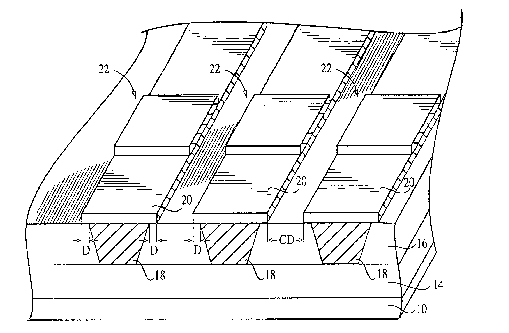
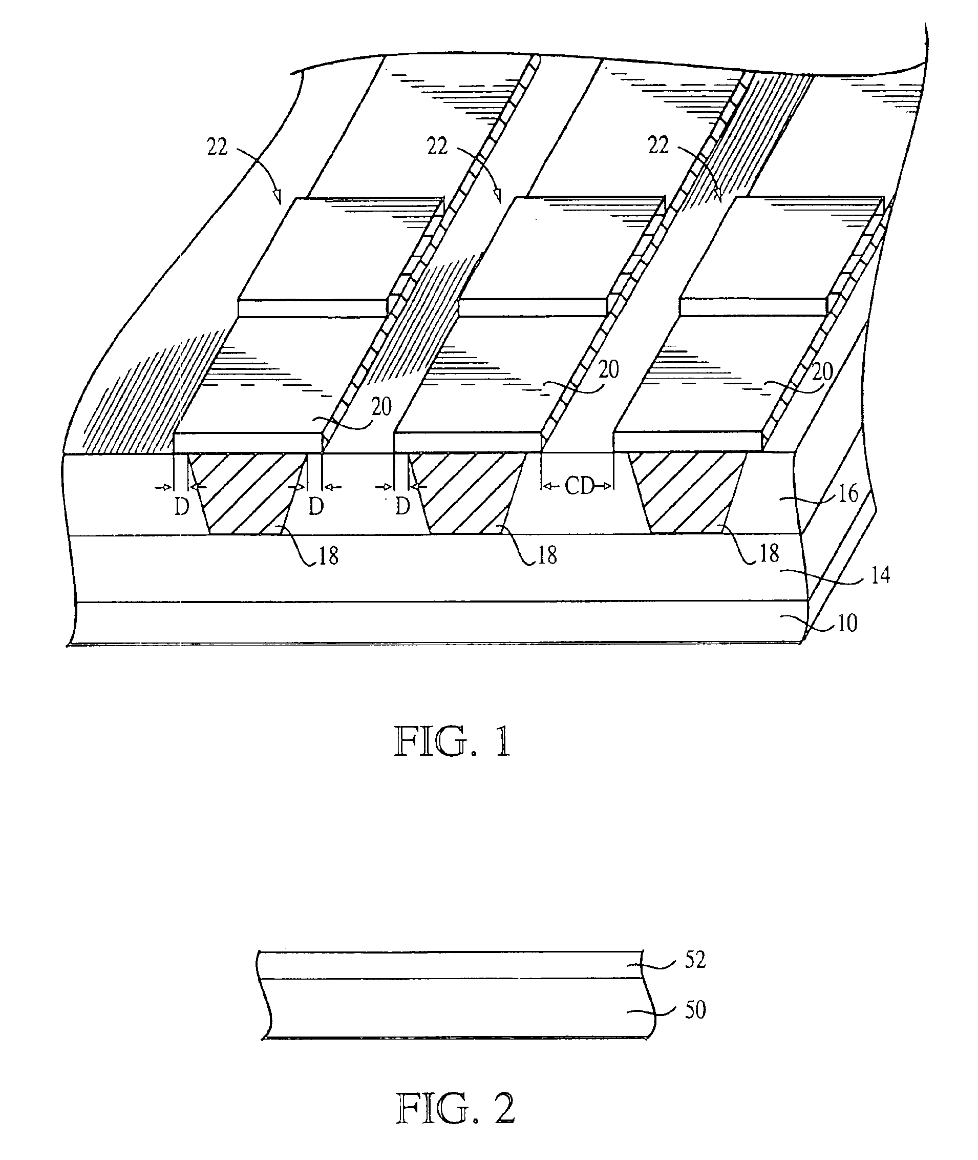
Although damascene processes are preferred for copper interconnects, in the MRAM cell context the damascene process poses a drawback, in that there is an overlay of the pinned layer 20 with respect to the associated digit line 18, which occurs primarily as a result of photoresist misalignment.
Because of technical and processing limitations, conventional damascene processing is also unable to obtain long digit lines and their respective pinned layers.
Another drawback of using a conventional damascene process to produce the digit lines 18 of an MRAM is the inability of the process to achieve a minimal space or minimum critical dimension CD (FIG. 1) between two adjacent digit lines and, consequently, between two adjacent memory cells.
However, with increased packing density of MRAM cells, the minimal space must decrease to values less than or equal to 0.1 μm, or even less than or equal to 0.05 μm, and current damascene processing does not afford these values with current 248 nm lithography.

Method used


Image

  • Minimally spaced MRAM structures
  • Minimally spaced MRAM structures
  • Minimally spaced MRAM structures

Examples


Embodiment Construction

[0031]In the following detailed description, reference is made to various exemplary embodiments of the invention. These embodiments are described with sufficient detail to enable those skilled in the art to practice the invention, and it is to be understood that other embodiments may be employed, and that structural and electrical changes may be made without departing from the spirit or scope of the present invention.

[0032]The term “substrate” used in the following description may include any semiconductor-based structure that has an exposed semiconductor surface. Structure must be understood to include silicon, silicon-on insulator (SOI), silicon-on sapphire (SOS), doped and undoped semiconductors, epitaxial layers of silicon supported by a base semiconductor foundation, and other semiconductor structures. The semiconductor need not be silicon-based. The semiconductor could be silicon-germanium, germanium, or gallium arsenide. When reference is made to substrate in the following de...


PUM


Abstract

A method of forming minimally spaced apart MRAM structures is disclosed. A photolithography technique is employed to define patterns an integrated circuit, the width of which is further reduced by etching to allow formation of patterns used to etch digit line regions with optimum critical dimension between any of the two digit line regions. Subsequent pinned and sense layers of MRAM structures are formed over the minimally spaced digit regions.

Description

[0001]This application is a continuation of application Ser. No. 10 / 454,479, filed on Jun. 5, 2003, now U.S. Pat. No. 6,750,069 which in turn is a divisional of application Ser. No. 09 / 828,823, filed on Apr. 10, 2001 (now U.S. Pat. No. 6,689,661 issued on Feb. 10, 2004), the disclosures of both of which are incorporated by reference herein.FIELD OF THE INVENTION[0002]The present invention relates MRAM semiconductor structures and, more particularly, to a method of forming minimally spaced MRAM structures.BACKGROUND OF THE INVENTION[0003]Magnetic random access memories (MRAMs) employ magnetic multilayer films as storage elements. When in use, an MRAM cell stores information as digital bits, which in turn depend on the alternative states of magnetization of thin magnetic multilayer films forming each memory cell. As such, the MRAM cell has two stable magnetic configurations, high resistance representing a logic state 0 and low resistance representing a logic state 1, or vice versa.[00...

Claims


Application Information

Patent Timeline
IPC IPC(8): H01L21/70H01L21/8246H01L27/22
CPCH01L27/222B82Y10/00H10B61/00
Inventor DURCAN, D. MARKDOAN, TRUNG T.LEE, ROGERKELLER, DENNISEARL, REN
Owner OVONYX MEMORY TECH LLC
Why Eureka
Try Eureka