Projection exposure apparatus and method
- Summary
- Abstract
- Description
- Claims
- Application Information
AI Technical Summary
Benefits of technology
Problems solved by technology
Method used
Image

Examples
first embodiment
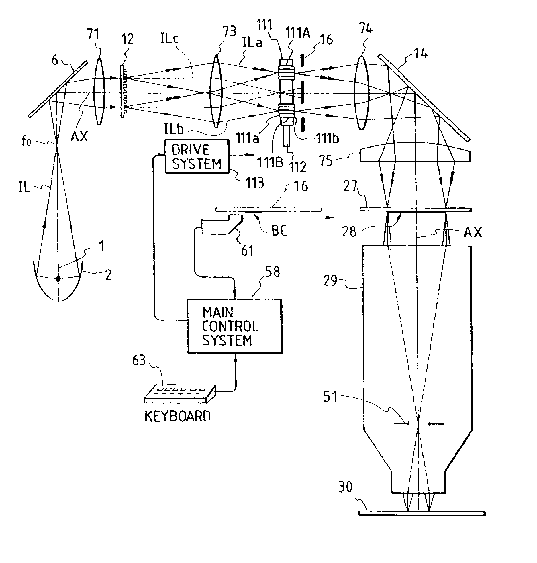
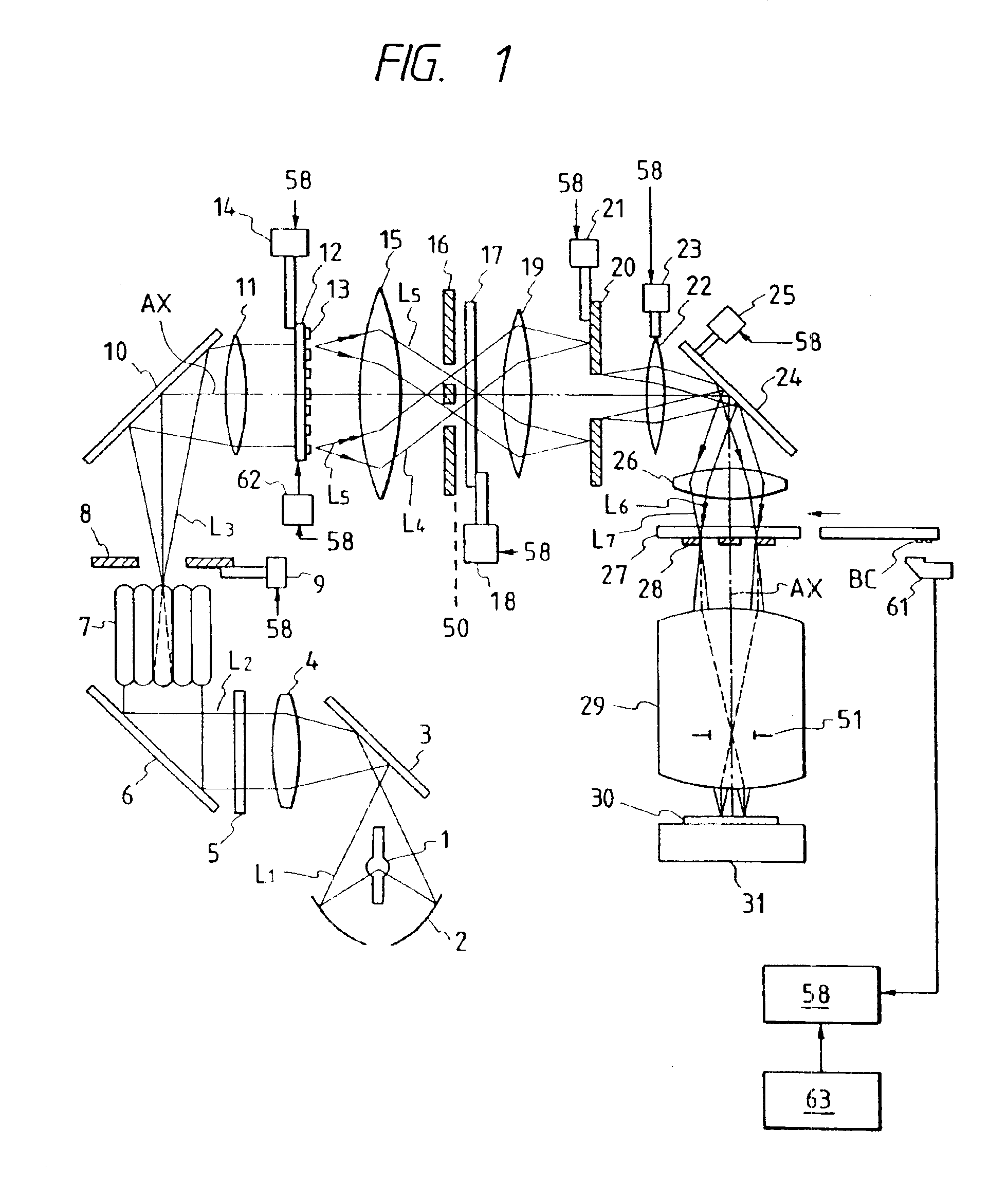
[0121]Embodiments of the present invention will hereinafter be described in detail with reference to the accompanying drawings. FIG. 1 is a block diagram illustrating a whole projection type exposure apparatus in accordance with the present invention. A luminous flux L1 emitted from an exposure light source 1 such a mercury lamp or the like and converged by an elliptical mirror 2 is reflected by a mirror 3. The luminous flux reflected by the mirror 3 passes through a relay lens 4 and is monochromatized by a wavelength selection element 5. A monochromatized luminous flux L2 is refracted by a mirror 6 and is incident on a fly eye lens 7. At this moment, an incident surface of the fly eye lens 7 is provided in a position substantially conjugate to reticle patterns 28. An exit surface of the fly eye lens 7 is formed on a Fourier transform corresponding plane (Fourier transform plane) of the reticle patterns 28 or in the vicinity of this plane. An aperture stop 8 is provided in close pro...
second embodiment
[0223]Next, an exposure method by use of the exposure apparatus in the second embodiment will be described with reference to FIGS. 19A and 19B.
[0224]FIGS. 19A and 19B are flowcharts each showing the exposure method in the embodiment of this invention. A difference between FIGS. 19A and 19B lies in whether the exposure is stopped or not when driving the reflector 54. In advance of the exposure, the shutter 52 is in such a status as to cut off the luminous flux L2. Determined herein are the number of positional changes of the reflector 54, coordinates of the respective positions of the reflector and exposure quantities for the respective coordinates (step 101). As stated before, however, if a so-called light quantity gravity of the illumination light when the luminous flux L5 corresponding to each position of the reflector 54 falls on the reticle 27 deviates from the optical axes AX of the illumination optical system and the projection optical system 29, there exists a possibility of ...
third embodiment
[0266]The individual fly eye lens groups 91A, 91B desirably assume the same configuration and are composed of the same material (refractive index). Respective lens elements of the individual fly eye lens groups 91A, 91B are double-convex lenses as in the Given therein is the example where the light-source-side focal surfaces 91a coincide with the incident surfaces, and the reticle-side focal surface 91b coincide with the exit surface. The fly eye lens elements may not strictly satisfy this relation but may be plano-convex lenses, convexo-plane lenses or plano-concave lenses. Note that the light-source-side focal surfaces 91a of the fly eye lens groups and the reticle-side focal surfaces thereof have, as a matter of course, the Fourier transform relation. Hence, in the example of FIG. 29, the reticle-side focal surfaces 91b of the fly eye lens groups—i.e., the exit surfaces of the fly eye lens groups 91A, 91B—have an image forming (conjugate) relation to the diffraction grating patt...
PUM
 Abstract
Description
Claims
Application Information