Compact optical gyroscope and method of manufacturing the same

a compact, optical technology, applied in the direction of optical elements, instruments, optical waveguide light guides, etc., can solve the problems of high cost of components, insufficient durability, and large dimensions of detecting sections, so as to reduce manufacturing costs, reduce manufacturing costs, and facilitate formation

Inactive Publication Date: 2005-04-26
SEIKO EPSON CORP
View PDF13 Cites 7 Cited by
  • Summary
  • Abstract
  • Description
  • Claims
  • Application Information

AI Technical Summary

Benefits of technology

[0038]According to the invention, the step of forming said detection light guide body preferably includes the step of forming said light guide path in which said light guide path sections are optically connected across a plurality of layers and the step of filling a protective material around said light guide path. By filling the protective material after forming the light guide path, a need for an assembly step is eliminated, and even a fine structure can be relatively easily configured.
[0039]According to the invention, at the step of forming said light guide path, said light guide path is preferably formed using an optical shaping process. By forming the light guide path using an optical shaping process, even a light guide path having a complicated configuration can be easily formed.
[0040]According to the invention, the step of forming said detection light guide body preferably includes the step of forming a plurality of said light guide layers having said light guide path sections and the step of alternately stacking said light guide layers such that said light guide path sections are optically connected to each oth...

Problems solved by technology

However, gyroscopes of this type have had problems in that component costs are high because of extremely high requirements on accuracy of their shapes and in that their durability is insufficient because of the presence of mechanically sliding sections.
However, in the case of an interference type gyroscope such as the optical fiber gyroscope disclosed on the above-cited Japanese Patent Publication No. 27194/1996, since it must have a great optical path length (which may range from several meters to several kilometers),...

Method used


Image

  • Compact optical gyroscope and method of manufacturing the same
  • Compact optical gyroscope and method of manufacturing the same
  • Compact optical gyroscope and method of manufacturing the same

Examples


first embodiment

[0072][First Embodiment of the Invention]

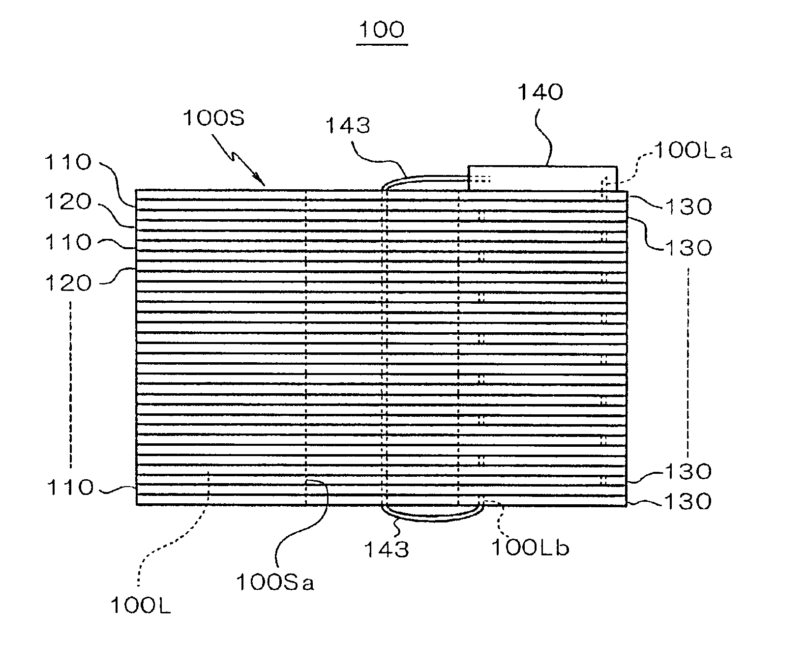
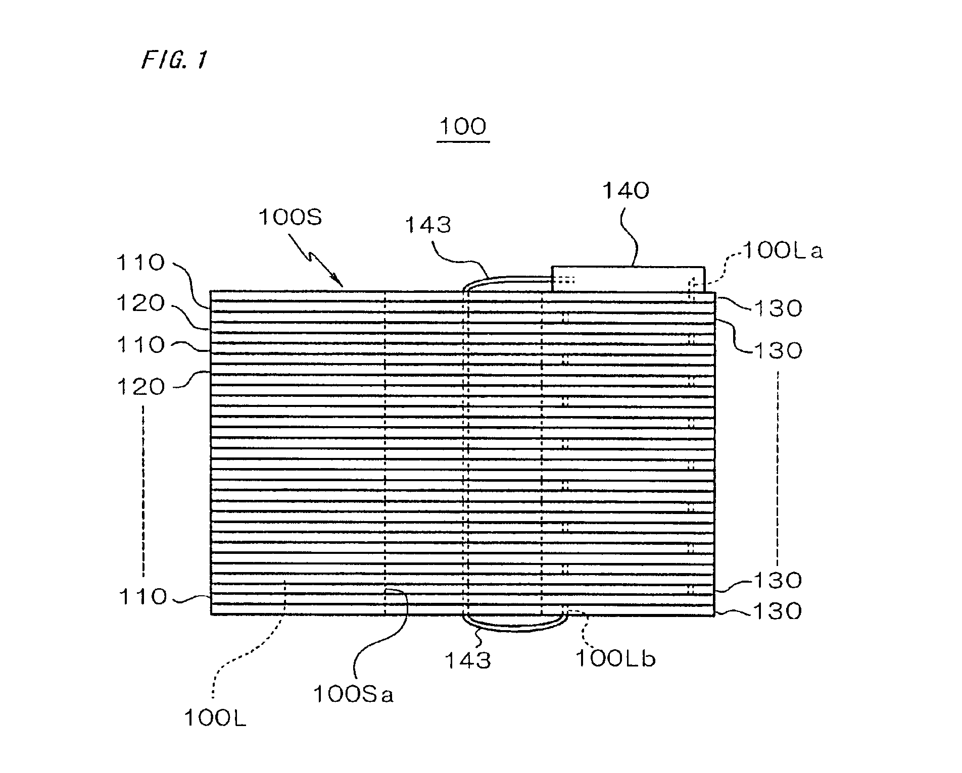
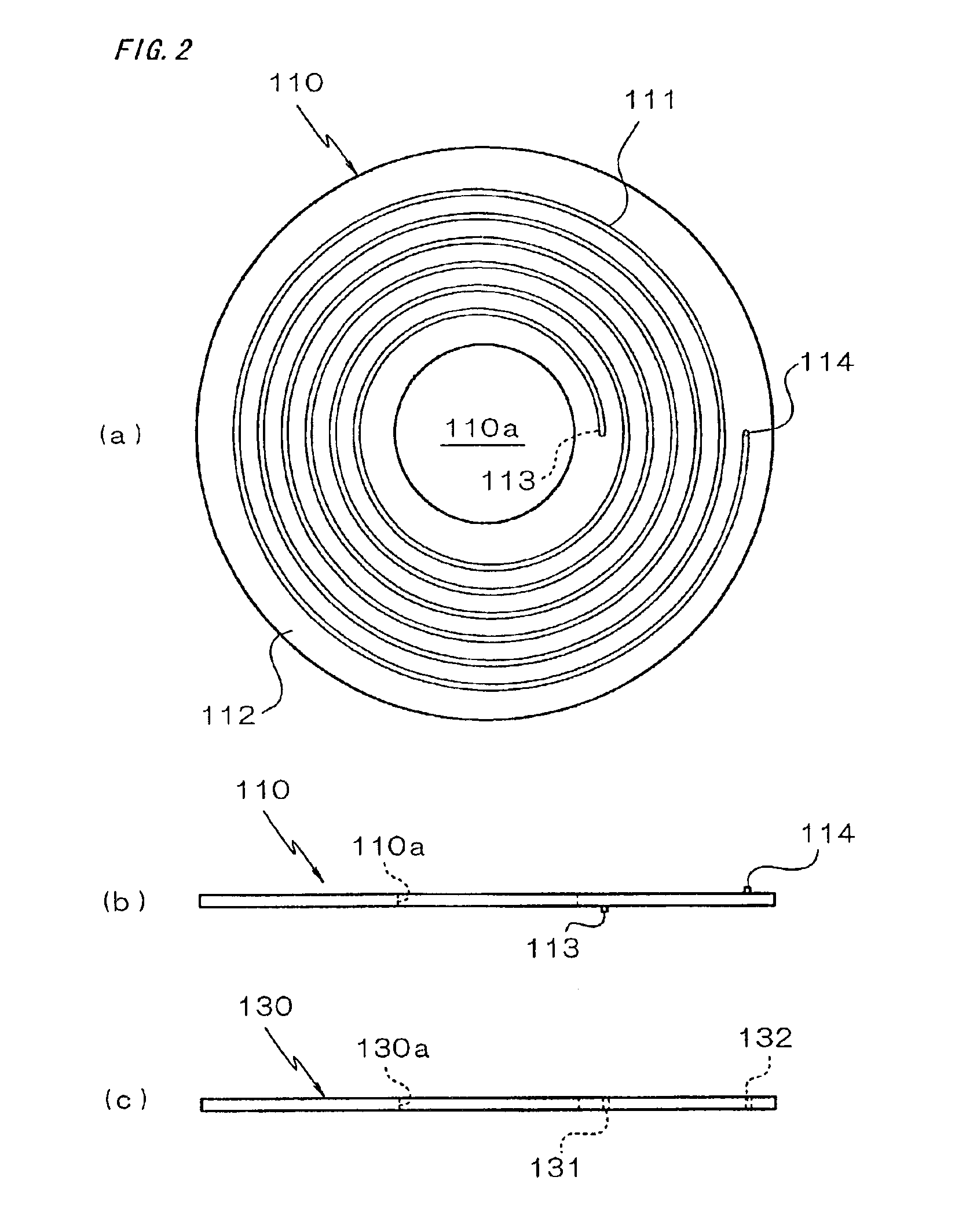
[0073]FIG. 1 is a front view of an optical gyroscope 100 of a first embodiment; FIG. 2 is a plan view (a) and a front view (b) of a light guide layer 110 that is one of elements of the optical gyroscope 100 and a front view (c) of a protective layer 130; and FIG. 3 is a plan view (a) and a front view (b) of a light guide layer 120 that is one of the elements of the optical gyroscope 100.

[0074]The optical gyroscope 100 has a detection light guide body 100S in which light guide layers 110 and light guide layers 120 are alternately stacked with protective layers 130 interposed therebetween. The detection light guide body 100S is formed in a cylindrical configuration as a whole, and a through hole 100Sa is provided in the middle of the same. A light guide path 100L having two ends 100La and 100Lb is formed inside the detection light guide body 100S, and one end 100La of the light guide path 100L protrudes from the top of the detection light guide...

second embodiment

[0096][Second Embodiment of the Invention]

[0097]An optical gyroscope 200 in a second embodiment will now be described with reference to FIG. 5 and FIG. 6. The optical gyroscope 200 has a detection light guide body 200S in which light guide layers 210 and 220 having the same configuration as that in the first embodiment are alternately stacked on a light measuring board 240 with protective layers 230 interposed therebetween. Since the detection light guide body 200S constituted by the light guide layers 210 and 220 and the protective layers 230 has substantially the same material and structure as those in the first embodiment, like parts will not be described here.

[0098]In the second embodiment, in the light measuring board 240, an optical circuit board 242 constituted by a piezoelectric body such as LiNbO3 is embedded substantially in the middle of a base substrate 241 constituted by an insulated substrate or the like; the optical circuit board 242 is optically connected to an inner...

third embodiment

[0109][Third Embodiment of the Invention]

[0110]A third embodiment of the invention will now be described with reference to FIGS. 10 to 13. In the third embodiment, a detection light guide body is configured by alternately stacking light guide layers 410 as shown in FIG. 10 and light guide layers 420 as shown in FIG. 11.

[0111]A light guide layer 410 is constituted by a plate-like light guide body and provided with a light guide path section 411 that is formed in a circular configuration. The periphery of the light guide path section 411 is protected with a protective material 412. The light guide path section 411 and the protective material 412 may be configured using the materials as described in the above embodiments of the invention. The light guide path section 411 is configured in the form of a helix or spiral that is wound in inward and outward directions in the plane of the same in the illustrated example. The light guide layer 410 has an annular configuration as a whole, and ...


PUM


Abstract

An optical gyroscope (100) has a detection light guide body (100S) and a light measuring board (140). The detection light guide body (100S) is formed by stacking light guide layers (110, 120) and protective layers (130) alternately. An eddy-shaped light guide path section is provided in each of the light guide layers (110, 120), and the light guide path sections are optically connected to each other through said protective layers (130) to form an integral light guide path (100L). One end (100La) of the light guide path (100L) is directly connected to the light measuring board (140), and another end (100Lb) of the same is connected to the light measuring board (140) through an optical fiber (143).

Description

TECHNICAL FIELD[0001]The present invention relates to an optical gyroscope and a method of manufacturing the same and, more particularly, to a stereoscopic configuration that is preferable as a structure of a sensing section such as a detection coil for detecting a rotary motion.BACKGROUND ART[0002]In general, rotating wheel type or mechanical type gyroscopes have been used for many years as gyroscopes. However, gyroscopes of this type have had problems in that component costs are high because of extremely high requirements on accuracy of their shapes and in that their durability is insufficient because of the presence of mechanically sliding sections.[0003]In order to solve the above problems, optical gyroscopes having a configuration for optically detecting attitude changes have been proposed. An optical gyroscope normally takes advantage of the Sagnac effect that is a phase difference generated between two light waves propagated in a closed optical loop in directions opposite to ...

Claims


Application Information

Patent Timeline
IPC IPC(8): G01C19/72G02B6/13G02B6/125G02B6/42G02B6/138G02B6/12H01S3/081H01S3/083
CPCG01C19/722G02B6/125G02B6/138G02B6/4214H01S3/083G02B2006/1219G02B6/4204
Inventor HASHIMOTO, YASUHARU
Owner SEIKO EPSON CORP
Why Eureka
Try Eureka