
Scale-based image filtering of magnetic resonance data

a magnetic resonance data and image filtering technology, applied in image enhancement, instruments, applications, etc., can solve the problems of low signal-to-noise ratio (snr) and/or contrast-to-noise ratio (cnr), image acquisition techniques often suffer from low snr and cnr, and degrade the information contained in images and their utility, etc., to achieve enhanced real-time images

Inactive Publication Date: 2005-04-26
THE TRUSTEES OF THE UNIV OF PENNSYLVANIA
View PDF9 Cites 22 Cited by
  • Summary
  • Abstract
  • Description
  • Claims
  • Application Information

AI Technical Summary

Benefits of technology

"The invention provides a new method for filtering MRI images that uses local structure information to improve image quality. The method uses a scale-based approach that adapts to the size of different structures in the image. The method outperforms existing methods and can be used in real-time MRI scanners. The resulting images have improved fine details and sharpness, even in the absence of motion or noise. The method can be automated and built into an MRI scanner. Overall, the invention provides a way to improve the quality of MRI images and preserve important details in the image."

Problems solved by technology

A variety of MRI protocols are currently available, however image acquisition techniques often suffer from low signal-to-noise ratio (SNR) and / or contrast-to-noise ratio (CNR).
A major drawback of filtering is that it often diffuses / blurs important structures along with noise.
Despite high adaptivity and robustness of the human visual perceptual system, low SNR and CNR often degrade the information contained in the image and its utility.
A major drawback of space-invariant filtering techniques is that, along with noise, they often blur important structures.
A significant drawback of this very useful approach, however, is that it does not offer any image-dependent guidance for selecting the optimum gradient magnitude.

Method used


Image

  • Scale-based image filtering of magnetic resonance data
  • Scale-based image filtering of magnetic resonance data
  • Scale-based image filtering of magnetic resonance data

Examples


example 1

Qualitative Comparisons.

[0089]In this example, two case studies are presented from MR patient studies, and then two phantom experiments are described.

[0090]Comparative Case Study 1.1.

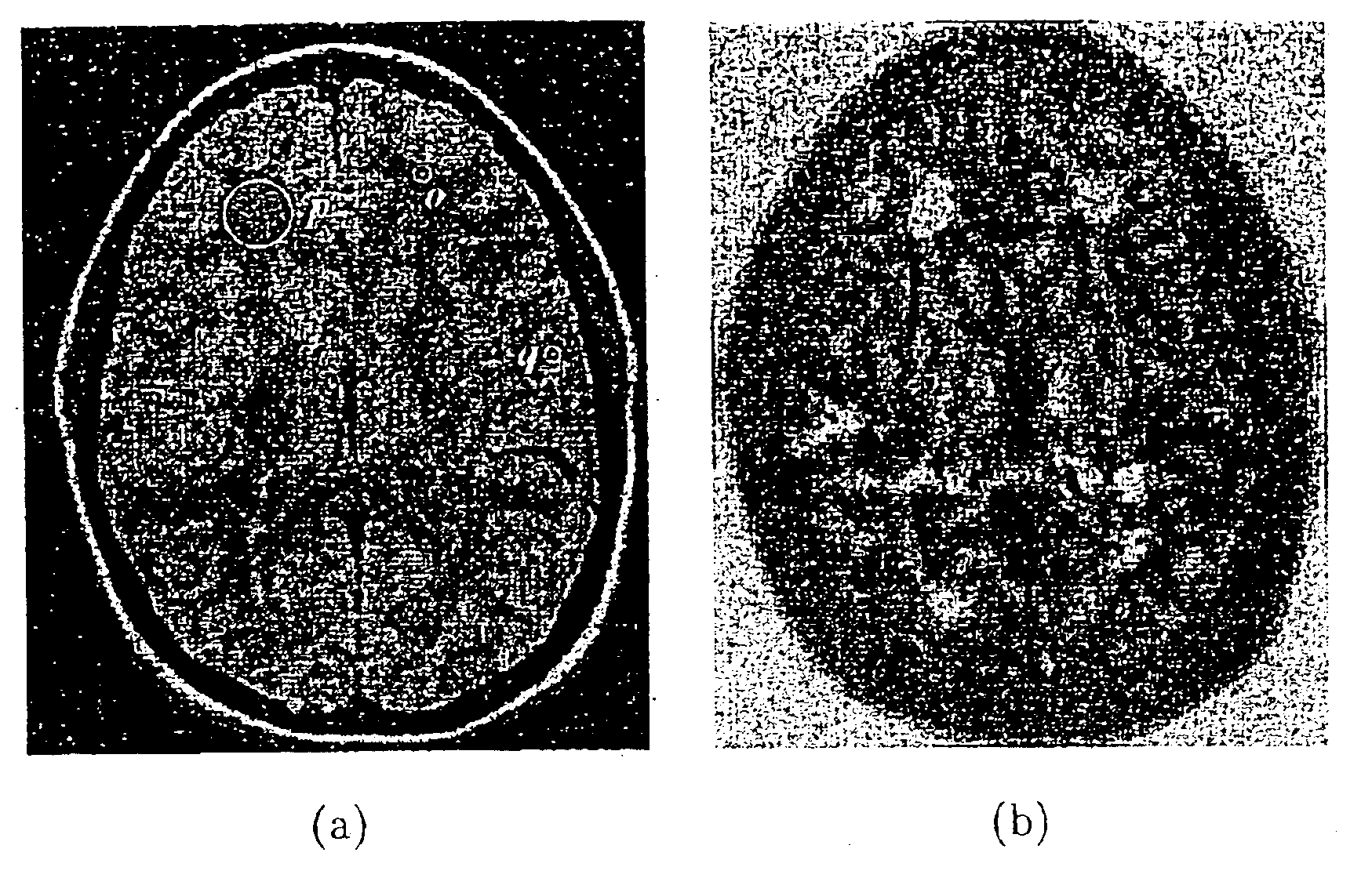
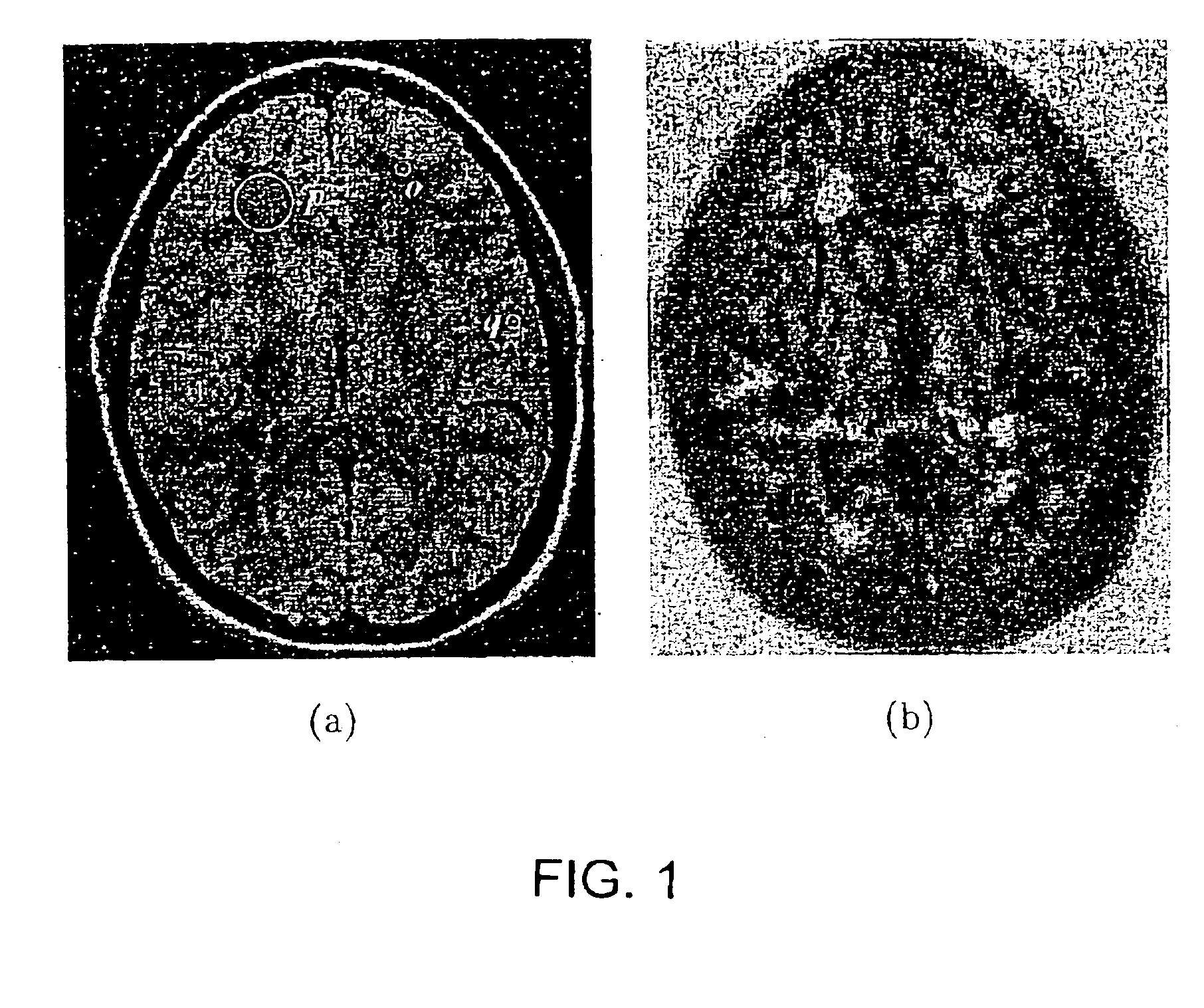
[0091]In FIG. 4, the filtered output from the three methods is illustrated for two regions of interest (ROI)—one from the top-left corner and the other from the bottom-right corner—selected from the MR slice displayed in FIG. 1(a). The two ROIs, and the results from the three filtering methods, are shown in FIGS. 4(a)-4(h). FIGS. 4(c)-4(h) depict filtered scenes (in 2D) corresponding to the scenes in FIGS. 4(a) and 4(b) resulting from anisotropic diffusion (shown in FIGS. 4(c) and 4(d)), from scale-based neighborhood averaging (shown in FIGS. 4(e) and 4(f)), and from scale-based diffusion (shown in FIGS. 4(g) and 4(h)). As can be seen from all six filtered images (FIGS. 4(c)-4(h)), the smoothness in homogeneous regions seems visually to be the same in all images, while boundary contrast seems to be high...

example 2

Quantitative Comparisons.

[0108]The quantitative comparison utilized the scenes depicted in FIGS. 6 and 7. Let Cb=(C, ƒb) denote the original binary phantom scene (before adding artifacts), and let E={Ci|Ci=(C, ƒi), 1≦i≦25} denote the set of 25 phantom scenes generated from Cb, as described in Example 1, Phantom Example 1.2. Let let Exi={Cxi|Cxi=(C, 71xi), 1≦i≦25} denot the set of scenes produced by applying the filtering method xε{ad, sa, sd} to the scenes in E, where ad, sa, sd correspond to anisotropic diffusion, scale-based neighborhood averaging and scale-based diffusion, respectively. Over the scene domain C, 100 ROIs, CHi, 1≦i≦100 were randomly selected, each of size 18×18, from homogeneous regions, such that all the pixels in a ROI had the same intensity (object or background) in the initial phantom scene Cb. Of the 100 ROIs, 60 were from background regions, and 40 were from object regions. Additionally, 50 ROIs, CSi, 1≦i≦50, were selected from regions containing boundaries. ...


PUM


Abstract

The invention provides novel scale-based filtering methods that use local structure size or “object scale” information to arrest smoothing around fine structures and across even low-gradient boundaries. One method teaches a weighted average over a scale-dependent neighborhood; while another employs scale-dependent diffusion conductance to perform filtering. Both methods adaptively modify the degree of filtering at any image location depending on local object scale. This permits a restricted homogeneity parameter to be accurately used for filtering in regions with fine details and in the vicinity of boundaries, while at the same time, a generous filtering parameter is used in the interiors of homogeneous regions.

Description

REFERENCE TO RELATED APPLICATIONS[0001]This application claims priority to U.S. Provisional Application No. 60 / 181,688 filed Feb. 7, 2000.GOVERNMENT SUPPORT[0002]This work was supported in part by a grants from the National Institutes of Health, grant number NS37172, and a grant from US Department of the Army, DAMD 179717271.FIELD OF THE INVENTION[0003]This invention relates generally to the field of magnetic resonance imaging (MRI), image display, image processing and image filtering to enhance structure and reduce noise.BACKGROUND OF THE INVENTION[0004]Magnetic Resonance Imaging (MRI) has revolutionized radiological imaging of the internal structures of the human body. It has the advantage of being noninvasive and offers no known health hazards. A variety of MRI protocols are currently available, however image acquisition techniques often suffer from low signal-to-noise ratio (SNR) and / or contrast-to-noise ratio (CNR). Although many acquisition techniques are available to minimize...

Claims


Application Information

Patent Timeline
Patent Type & Authority Patents(United States)
IPC IPC(8): A61B5/055G06T5/00
CPCA61B5/055G06T5/20G06T2207/10088G06T2207/20012G06T2207/20192G06T2207/30016G06T5/70
Inventor SAHA, PUNAM KUMARUDUPA, JAYARAM K.
Owner THE TRUSTEES OF THE UNIV OF PENNSYLVANIA
Learn More