Self-propelled operating machine

a self-propelled operating machine and operating system technology, which is applied in mechanical equipment, gearing details, transportation and packaging, etc., can solve the problems of increasing the number of fixing parts, the size of the self-propelled operating machine is large, and the hydraulic oil cooler is not equipped, so as to reduce the installation space of the oil cooler, reduce the size of the self-propelled operating machine, and reduce the effect of fixing parts

Inactive Publication Date: 2005-05-03
HONDA MOTOR CO LTD
View PDF11 Cites 10 Cited by
  • Summary
  • Abstract
  • Description
  • Claims
  • Application Information

AI Technical Summary

Benefits of technology

[0009]By providing the cooling passage for cooling the hydraulic oil of the hydraulic CVT passed therethrough in the stand for mounting the power source on the transmission mechanism, the stand can also serve as an oil cooler for cooling the hydraulic oil. This eliminates the need for an oil cooler for that single purpose and an oil cooler mounting member. Installation space for the oil cooler can thus be reduced with the simple configuration to reduce the size of the self-propelled operating machine and also reduce the number of components and production costs.
[0010]Further, by mounting the stand also serving as an oil cooler and the hydraulic CVT on the transmission mechanism and extending the stand to a higher level than the hydraulic CVT to mount the power source, the power source, hydraulic CVT and transmission mechanism constituting the power train can be put together. The simple configuration can thus further reduce the installation space for the power train to reduce the size of the self-propelled operating machine, and also simplify the fixing structure of fixing the power train.
[0011]The stand is preferably configured to enclose the hydraulic CVT. Since the stand also serves as an oil cooler, the distance between the oil cooler and the hydraulic CVT can be reduced. An oil pipe between the oil cooler and the hydraulic CVT can thus be shortened.
[0012]The self-propelled operating machine of the present invention preferably further comprises: an output shaft extending downward from the power source; and input shaft extending upward from the hydraulic CVT and to which the output shaft is connected; and an air cooling fan mounted on the output shaft or input shaft for sending air from top to bottom. That is, the cooling fan is interposed between the power source and the hydraulic CVT. The inner wall surface of the oil cooler, the undersurface of the drive source and the outer surface of the hydraulic CVT can thus be forcedly cooled, resulting in efficient cooling thereof. Further, there is no need to provide an additional space for disposing the air cooling fan. The air cooling fan can thus be easily disposed in such a narrow space enclosed by the stand. Further, the stand can enclose the air cooling fan, thereby also servicing as a fan cover. This eliminates the need for a fan cover, reducing the number of components.
[0013]Further, in the present invention, the self-propelled operating machine preferably further comprises left and right operating handles extending rearward from the stand to allow an operator to control the operating handles while walking. That is, there is less limitation in mounting space of the operating handles as compared with the case of extending the operating handles from the body of the operating machine. The mounting space of the operating handles can thus be more easily provided.
[0014]Further, in the present invention, the self-propelled operating machine preferably further comprises: guide grooves of a T shape in cross section formed to extend over the height of the stand; and fasteners for fixing the operating handles, fitted into the guide grooves movably along the guide grooves while restricted in rotation within the guide grooves; wherein, the operating handles are supported at a desired position on the stand with the fasteners. Thus allowing the operating handles to be secured at a desired position to the stand with the fasteners facilitates the adjustment in height of the operating handles. An operator can desirably adjust the height of the operating handles according to his or her preference.

Problems solved by technology

This power agricultural machine is not equipped with an oil cooler for cooling hydraulic oil.
This inevitably makes the size of the self-propelled operating machine 300 large.
This, however, renders the configuration of fixing the units 305, 306 and 309 complex and increases the number of fixing parts and the production costs, leaving room for improvement.

Method used


Image

  • Self-propelled operating machine
  • Self-propelled operating machine
  • Self-propelled operating machine

Examples


Embodiment Construction

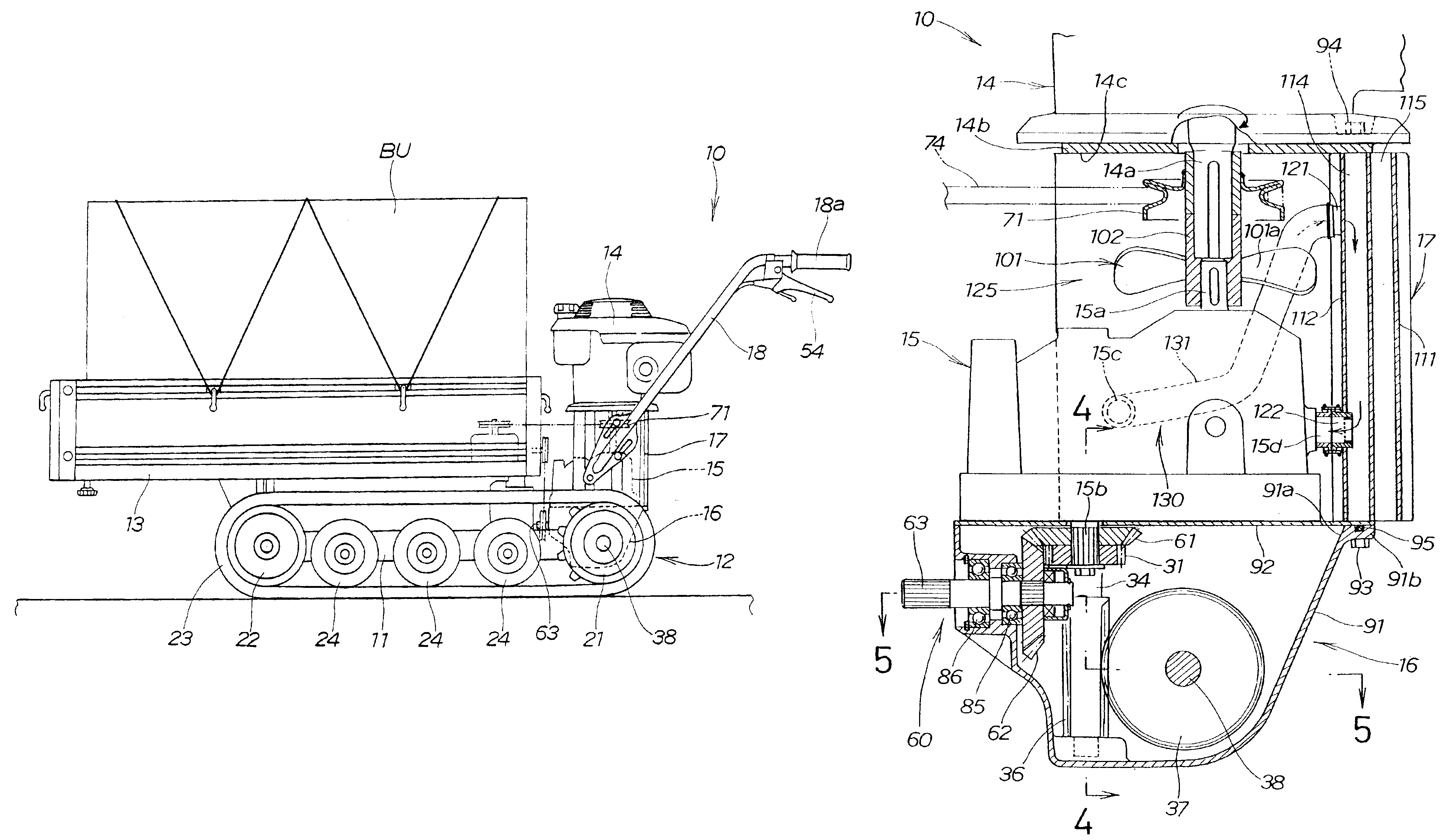
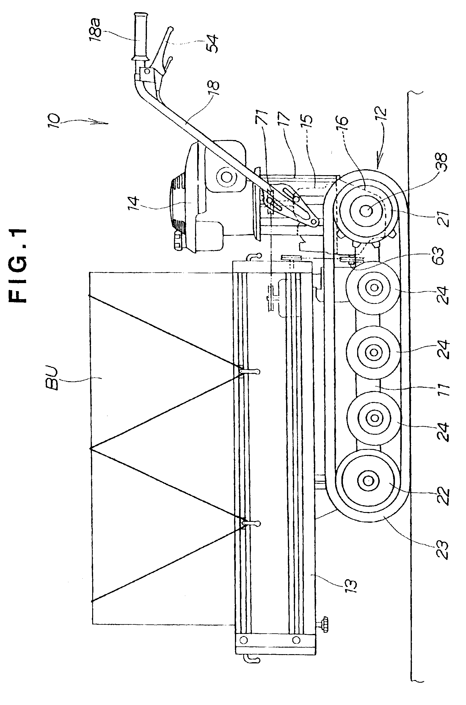
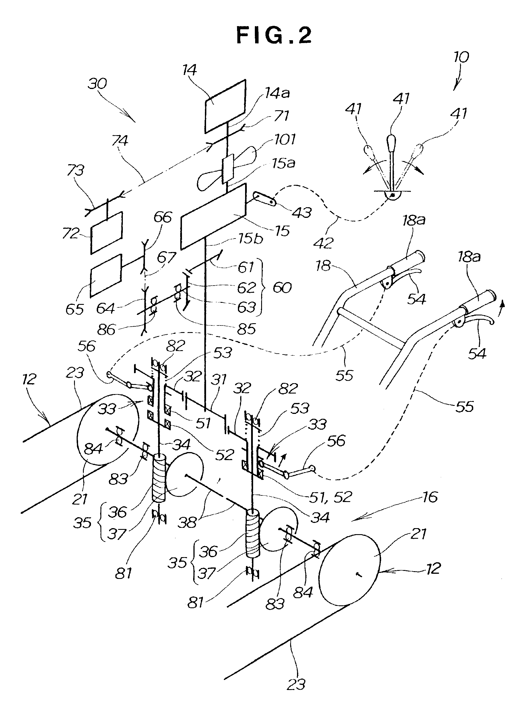
[0028]FIG. 1 illustrates a crawler-type carrier vehicle exemplifying a self-propelled operating machine 10. The carrier vehicle 10 includes a pair of left and right crawler belt units 12, 12 (see FIG. 2) provided at a body frame 11, a load-carrying platform 13 mounted on top of the body frame 11, an engine 14, hydraulic CVT 15, transmission mechanism 16 and stand 17 mounted on a rear portion of the body frame 11, and operating handles 18 extending obliquely rearward and upward from the stand 17.

[0029]The engine 14 is a drive source for the self-propelled operating machine 10. The self-propelled operating machine 10 is driven by the engine 14 via the pair of left and right crawler belt units 12, 12 for self propulsion. More specifically, the crawler carrier vehicle 10 shown in FIG. 1 is a walk-behind self-propelled operating machine which is maneuvered by an operator not shown walking with the operating handles 18.

[0030]Each crawler belt unit 12 includes a drive wheel 21 mounted at t...


PUM


Abstract

A self-propelled operating machine has a power source, a hydraulic CVT for varying power outputted from the power source, and a transmission mechanism connected to the hydraulic CVT for transmitting power outputted from the hydraulic CVT. A stand is mounted between the transmission mechanism and the power source so as to enclose the hydraulic CVT. The stand has an oil passage through which hydraulic oil of the hydraulic CVT flows. A cooling fan cools the oil passage of the stand to thereby cool the hydraulic oil of the hydraulic CVT flowing through the oil passage. The cooling fan is disposed between the power source and the hydraulic CVT so as to be enclosed by the stand.

Description

BACKGROUND OF THE INVENTION[0001]The present invention relates to self-propelled operating machines, such as carrier vehicles, snowplows and cultivators, which are propelled by power from power sources, and more particularly, to self-propelled operating machines configured to transmit power from power sources via hydraulic systems and hydraulic CVTs (Continuous Variable Transmissions) to transmission mechanisms and to transmit the power from the transmission mechanism to axles and various loads.BACKGROUND INFORMATION[0002]A self-propelled operating machine identified as a “Power Agricultural Machine with Hydraulic System” is disclosed, for example, in Japanese Utility Model Laid-Open Publication No. SHO-56-13137. This power agricultural machine is not equipped with an oil cooler for cooling hydraulic oil. To prevent the heating of hydraulic oil, it is required to employ a hydraulic system having a sufficient reserve output.[0003]As a self-propelled operating machine having an oil co...

Claims


Application Information

Patent Timeline
Patent Type & Authority Patents(United States)
IPC IPC(8): B60K17/04B62D51/00B62D51/06F16H57/04F16H61/40F16H61/4165
CPCB60K17/04B62D51/001F16H57/04F16H61/4165B62D51/06Y10T74/2186
Inventor SUGIMOTO, YASUHIROSUESHIGE, HIROSHI
Owner HONDA MOTOR CO LTD
Why Eureka
Try Eureka