
Human power amplifier for lifting load with slack prevention apparatus

a technology of slack prevention and human power amplifier, which is applied in the direction of lifting equipment, load-engaging elements, gripping heads, etc., can solve the problems of limiting the acceleration and deceleration of heavy objects by the operator's strength, the system is not suited to maneuvering objects of various weights, and the balancer is not easily changed, so as to prevent slack in the line

Inactive Publication Date: 2005-05-03
GORBEL INC
View PDF21 Cites 61 Cited by
  • Summary
  • Abstract
  • Description
  • Claims
  • Application Information

AI Technical Summary

Benefits of technology

[0010]A signal representing the vertical force imposed on the end-effector by the human operator, as measured by a sensor, is transmitted to the controller that is associated with the actuator. In operation, the controller causes the actuator to rotate the pulley and move the end-effector appropriately so that the human operator only lifts a pre-programmed small proportion of the load force while the remaining force is provided by the actuator. Therefore, the actuator assists the operator during lifting movements in response to the operator's hand force. Moreover, the tensile force in the line is detected or estimated, for example, by detecting the energy or current that is drawn by an actuator. In addition, because load force is a dominating factor in establishing the magnitude of tensile force, load force can be used to roughly approximate tensile force and vice versa. Hereinafter, it should be understood that tensile force can be estimated using load force and load force can be estimated using tensile force. A signal representing the load force or tensile force on the line is sent to the controller, and the controller uses the load force or tensile force signal to drive the actuator effectively in response to the human input. This, for example, can prevent the actuator from releasing line when the load force or tensile force is zero so that although the line may become loose (i.e. not taut), slack (as defined above) will never be created in the line.

Problems solved by technology

Therefore, a heavy object's acceleration and deceleration is limited by the operator's strength.
Second, if the system is electrically powered, the right amount of voltage is provided to the amplifier to generate a lift force that equals the load weight.
The fixed preset forces of balancers are not easily changed in real time, and therefore these types of systems are not suited for maneuvering of objects of various weights.
If the operator does touch the object, the force reading will be incorrect.
Unlike the assist device of this application, balancers do not give the operator a physical sense of the force required to lift the load.
Also, unlike the device of this application, balancers can only cancel the object's weight with the line's tension and are not versatile enough to be used in situations in which load weights vary.
Although suitable for lifting objects of various weights, this type of system is not comfortable for the operator because the operator has to focus on an intermediary device (i.e., valve, push-button, keyboard, or switch).
Thus, the operator pays more attention to operating the intermediary device than to the speed of the object, making the lifting operation rather unnatural.
A problem occurs when the operator presses downward on the end-effector to engage the load with the suction cups, the controller and actuator interpret this motion as an attempt to lower the load.
As a result, the actuator causes the pulley to release more line than necessary, creating “slack” in the cable.
After the slack is produced in the line by this or other circumstances, when the operator pushes upwardly on the handle, the slack line can become tight around the operator's neck or hand creating deadly injuries.
These occurrences will cause slack in the line since the operator pushes downwardly on the end-effector handle to situate a box, while the end-effector is constrained from moving downwardly.
In general, slack in the line can be dangerous for the operator and others the same work environment.
The force sensor devices of this class also fail to give an operator a realistic sense of the weight of the load being lifted.
This can lead to unnatural and possibly dangerous load maneuvers.

Method used


Image

  • Human power amplifier for lifting load with slack prevention apparatus
  • Human power amplifier for lifting load with slack prevention apparatus
  • Human power amplifier for lifting load with slack prevention apparatus

Examples


first embodiment

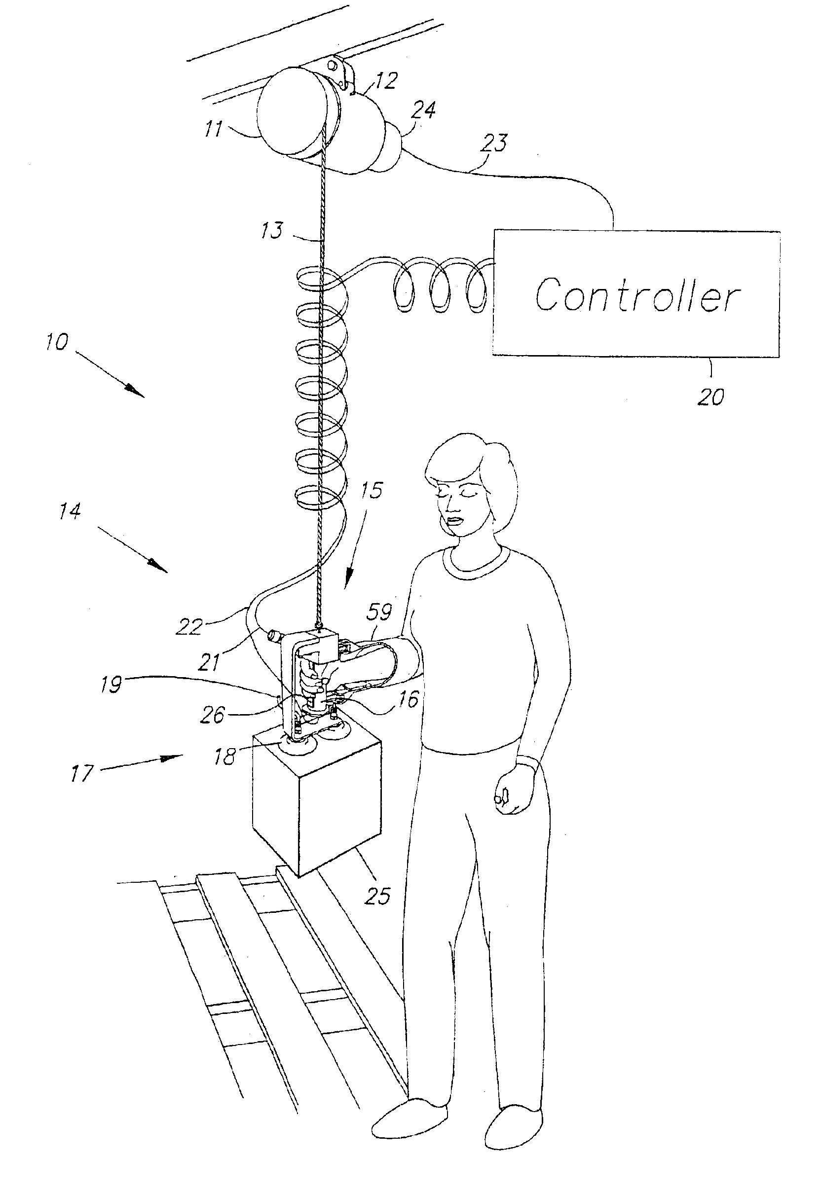
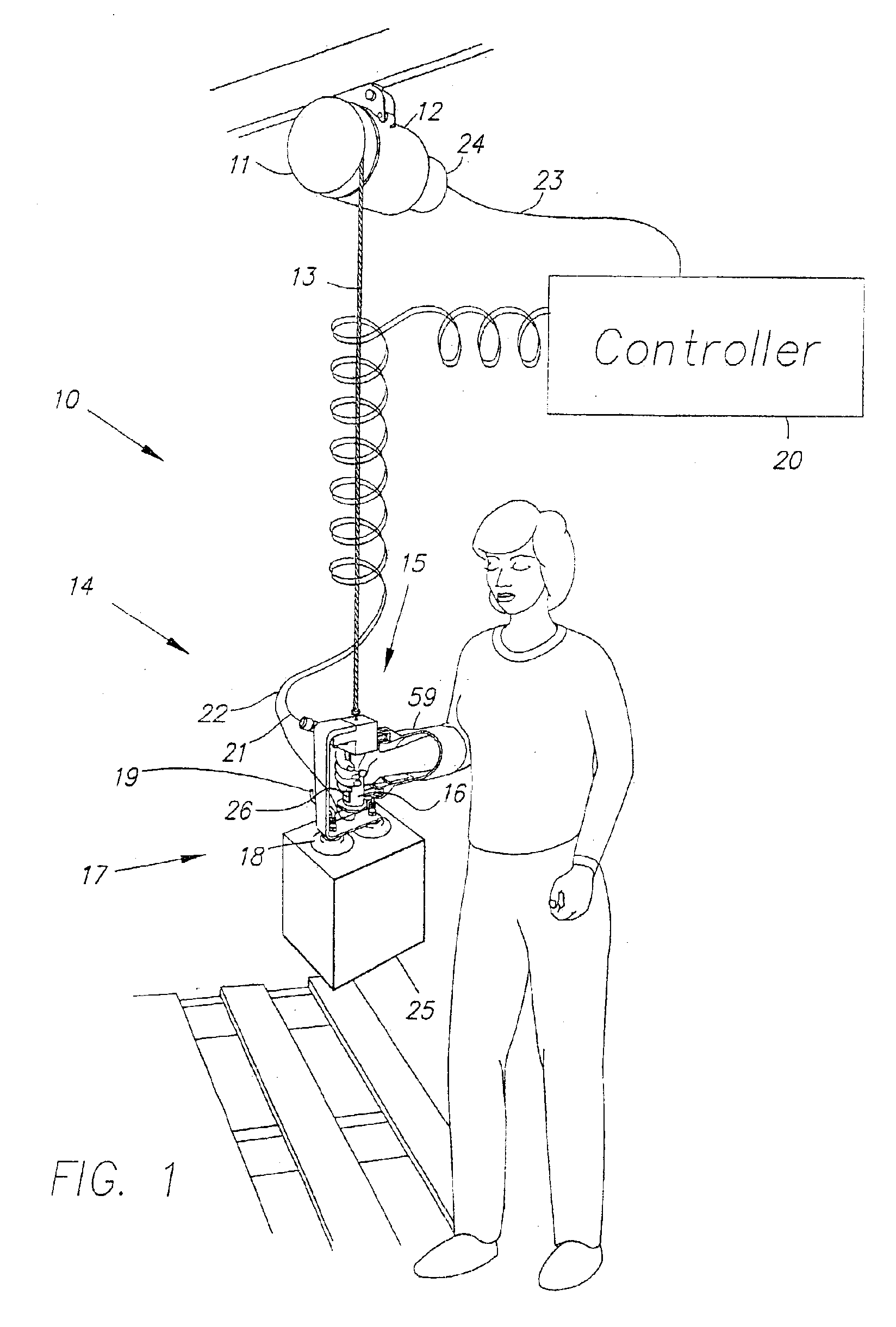
[0038]FIG. 1 illustrates the invention, showing a human power amplifier 10. At the top of the device, a take-up pulley 11, driven by an actuator 12, is attached directly to a ceiling, wall, or overhead crane. Encircling pulley 11 is a line 13. Line 13 is capable of lifting or lowering a load 25 when the pulley 11 turns. Line 13 can be any type of line, wire, cable, belt, rope, wire line, cord, twine, string or other member that can be wound around a pulley and can provide a lifting force to a load. Attached to line 13 is an end-effector 14, that includes a human interface subsystem 15 (including a handle 16) and a load interface subsystem 17, which in this embodiment includes a pair of suction cups 18. Also, shown is an air hose 19 for supplying suction cups 18 with low-pressure air.

[0039]In the preferred embodiment, actuator 12 is an electric motor with a transmission, but alternatively it can be an electrically-powered motor without a transmission. Furthermore, actuator 12 can als...

experiment 1

[0073

[0074]If Δv=0 for two different objects being maneuvered (i.e. the operator maintains similar operational speeds), then:

0=(GK+S)(Δf)+S(ΔW)  (12)

[0075]Rearranging the terms of equation (12) results in equation (13): GKS+1=-Δ⁢ ⁢WΔ⁢ ⁢f(13)

[0076]Equation (13) indicates that an increase or a decrease in the load weight (ΔW) will lead to an increase or a decrease in the upward human force, if operational speed is expected to remain unchanged. In other words, if the load weight is increased, the operator needs to increase his / her upward hand force or decrease his / her downward force to maintain the same operational speed. The term (GK / S+1) in equation (13) is the force amplification factor. The larger (K) is chosen to be, the greater the force amplification in the system will be. Consequently, if the force amplification is large, the operator “feels” only a small percentage of the change of the load weight. Essentially, the operator still retains a sensation of the dynamic characterist...

experiment 2

[0077

[0078]If Δf=0, (i.e. operator decides to maintain similar forces on the end-effector for two different load weights), then equation (11) reduces to:

(1+SE)Δv=S(ΔW)  (14)

[0079]This means that an increase in load weight, (ΔW), will lead to an increase of downward speed, if the operator maintains a constant hand force. Moreover an increase or decrease in the weight of the load, (ΔW), will cause a decrease or increase, respectively, in the upward end-effector speed for a given operator force on the end-effector. Essentially, the load falls faster and goes up slower if there is an increase in the load weight for a given operator force. From equations (13) and (14), it can be deduced that for an increase of load weight, the operator needs either to increase his / her upward force to maintain similar operational speed or to decrease his / her upward operational speed to maintain similar force on his / her hand. This dynamic behavior is very comforting and natural for the workers.


PUM


Abstract

A human power amplifier includes an end-effector that is grasped by a human operator and applied to a load. The end-effector is suspended, via a line, from a take-up pulley, winch, or drum that is driven by an actuator to lift or lower the load. The end-effector includes a force sensor that measures the vertical force imposed on the end-effector by the operator and delivers a signal to a controller. The controller and actuator are structured in such a way that a predetermined percentage of the force necessary to lift or lower the load is applied by the actuator, with the remaining force being supplied by the operator. The load thus feels lighter to the operator, but the operator does not lose the sense of lifting against both the gravitation and inertial forces originating in the load.

Description

RELATED APPLICATIONS[0001]This application is a Division of parent application Ser. No. 10 / 071,311, filed Feb. 8, 2002 by Homayoon Kazerooni, entitled Human Power Amplifier For Lifting Load With Slack Prevention Apparatus, now U.S. Pat. No. 6,622,990 which is a Division of parent application Ser. No. 09 / 443,278, filed Nov. 18, 1999, now U.S. Pat. No. 6,386,513, entitled Human Power Amplifier For Lifting Load Including Apparatus For Preventing Slack In Lifting Cable which parent application claims the benefit of U.S. Provisional Application Nos. 60 / 134,002, filed on May 13, 1999, No. 60 / 146,538, filed on Jul. 30, 1999, and No. 60 / 146,541, filed on Jul. 30, 1999. Both the parent and provisional applications are hereby incorporated by reference.FIELD OF THE INVENTION[0002]The present invention relates to material handling devices that lift and lower loads as a function of operator-applied force.BACKGROUND OF THE INVENTION[0003]The device described here is different from manual material...

Claims


Application Information

Patent Timeline
IPC IPC(8): B66D3/00B66D3/18B66C1/00B66C1/02
CPCB66C1/0212B66C1/0243B66D3/18B66C1/0275B66C1/0256
Inventor KAZEROONI, HAMAYOON
Owner GORBEL INC
Learn More