Filter apparatus for removing sulfur-containing compounds from liquid fuels, and methods of using same

a technology of liquid fuel filter and sulfur-related compounds, which is applied in the direction of filtration separation, machine/engine, separation process, etc., can solve the problems of adversely affecting the useful life of post-combustion emission control devices such as catalytic converters, small concentrations of sulfur-related compounds in gasoline may generate “rotten egg” or other objectionable odors in vehicle exhaust, and achieve the effect of reducing the concentration of sulfur compounds

Inactive Publication Date: 2005-05-03
FRAM GROUP IP
View PDF33 Cites 28 Cited by
  • Summary
  • Abstract
  • Description
  • Claims
  • Application Information

AI Technical Summary

Benefits of technology

[0017]The present invention provides an in-line fuel filter, for filtering a liquid fuel at a point of use thereof, and for reducing the concentration of sulfur compounds therein. One particularly preferred application, in which the filter hereof is adapted to be used, is on a vehicle.
[0020]A fuel filter according to the present invention further includes filter media, disposed in the housing chamber, for filtering liquid fuel and for removing sulfur compounds therefrom. The filter media has a sulfur-treating composition thereon for reacting with sulfur-containing compounds, and for reducing the amount of sulfur-containing compounds present in the fuel.

Problems solved by technology

The useful life of post-combustion emission control devices, such as catalytic converters, is adversely affected by the presence of sulfur-containing compounds in vehicle exhaust.
Furthermore, it is well known that very small concentrations of sulfur-related compounds in gasoline may generate “rotten egg” or other objectionable odors in vehicle exhaust.
Sulfur-containing compounds, if present in fuel, are likely to adversely affect such new technologies.
Although petroleum refiners continue to work on sulfur removal, little has been done in the area of post-refinery fuel filtration to remove sulfur-containing compounds from fuels at a point of use thereof.
There have been some limited efforts to filter sulfur and other contaminants out of gasoline by the end user, after the gas has been installed in a vehicle.

Method used


Image

  • Filter apparatus for removing sulfur-containing compounds from liquid fuels, and methods of using same
  • Filter apparatus for removing sulfur-containing compounds from liquid fuels, and methods of using same
  • Filter apparatus for removing sulfur-containing compounds from liquid fuels, and methods of using same

Examples


first embodiment

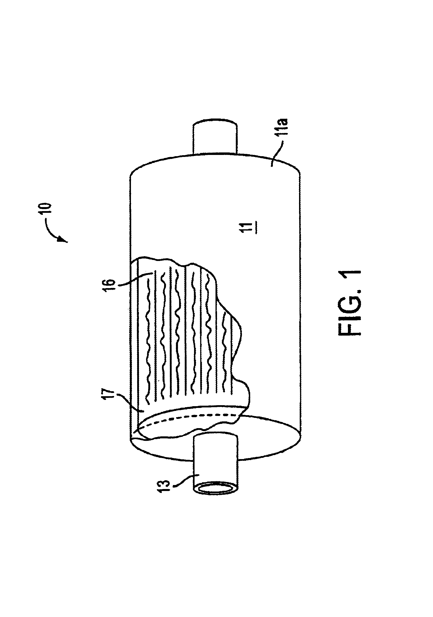
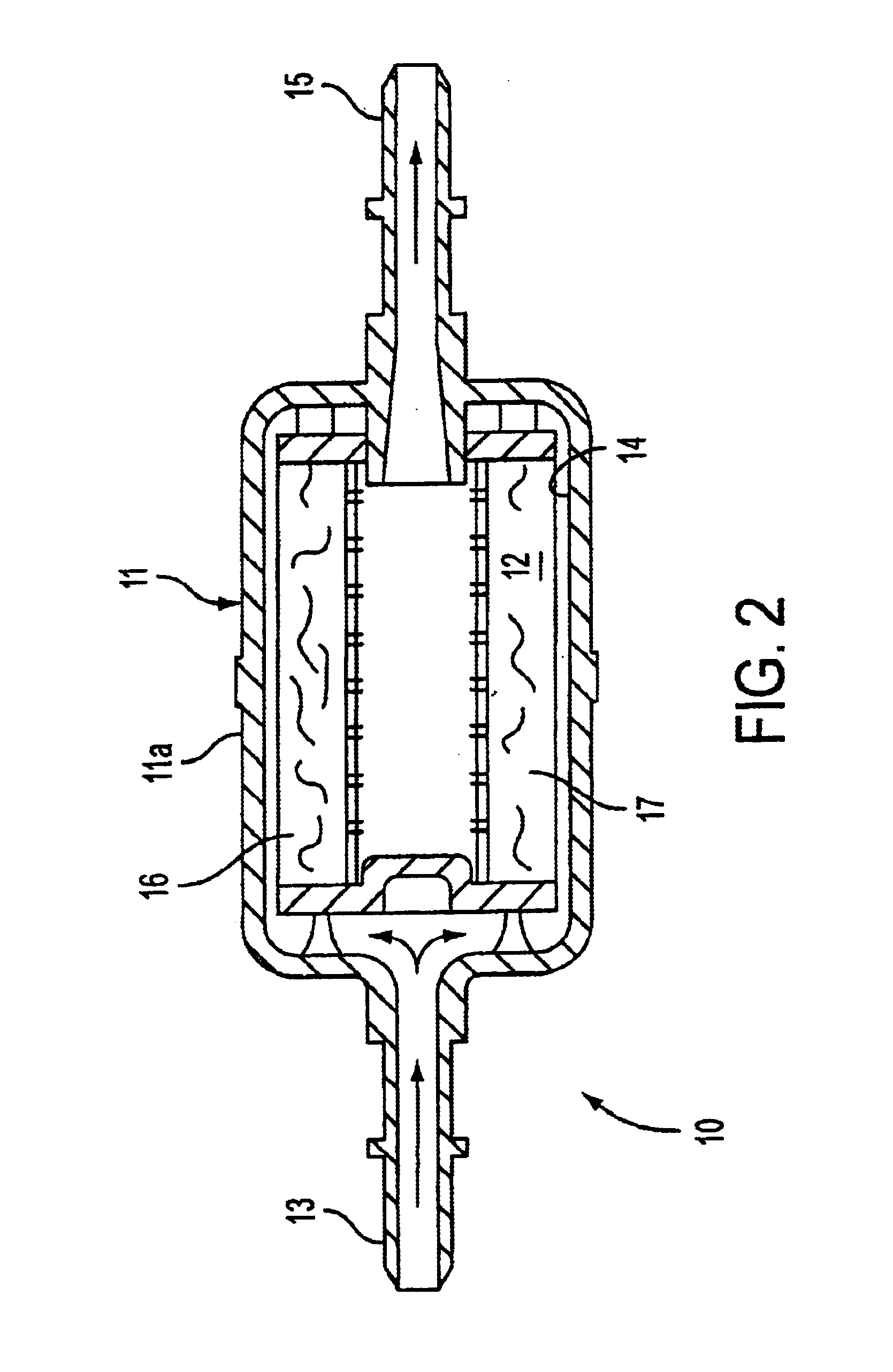
[0038]Referring now to FIGS. 1-2 of the drawings, a sulfur-reducing fuel filter, according to a first embodiment of the present invention, is shown generally at 10. The fuel filter 10 is provided to filter a liquid fuel at a point of use thereof, and to remove sulfur compounds therefrom.

[0039]The direction of fuel flow through the filter is shown by the arrows in FIG. 2.

[0040]Illustrative and non-limiting examples of liquid fuels, which the filter 10 may be used to filter, include gasoline, diesel fuel, methanol, ethanol, fuel oil, and mixtures thereof.

[0041]One particularly preferred application, in which the filter hereof is adapted to be used, is on a vehicle. Another application is to filter a liquid hydrocarbon-based fuel, in preparation for using the fuel to power a fuel cell.

[0042]A fuel filter 10 according to the embodiment of FIGS. 1-2 includes a thin-walled hollow housing 11, including a housing body 11a defining a chamber 14 therein. The housing 11 may have electrically c...

second embodiment

[0070]A fuel filter 110, which is a modified variation of the basic filter design of FIG. 1, is shown in FIGS. 8-9. In this variation, the housing 11 is exactly the same as discussed above in connection with the first embodiment, but the filter element 117 is different. In the embodiment of FIGS. 8-9, the filter element 117 includes two relatively thin spaced-apart layers of fiber webbing 112, 113, which define a storage area 115 therebetween.

[0071]In this embodiment, the fibers making up the fiber webbing 112, 113 may be the shaped wicking fibers 20 discussed above, or alternatively, may be conventional non-woven fibers. Where the wicking fibers 20 are used for the webbing 112, 113, a plurality of solid particles 18 and / or one or more sulfur-treating reagents may be disposed within the cavities 22 thereof, as previously discussed.

[0072]In this embodiment, the two spaced-apart layers of fiber webbing 112, 113 cooperate to retain an inner layer of particles 118 therebetween in the st...

third embodiment

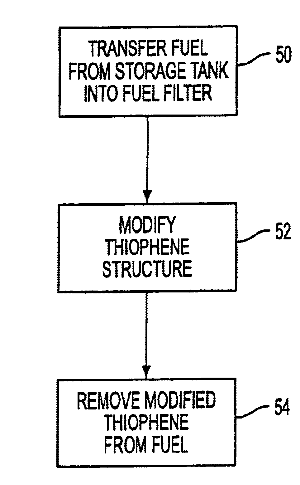
[0076]Referring now to FIG. 10, a fuel filter in accordance with a third embodiment of the invention is shown generally at 210. In the embodiment of FIG. 10, the fuel filter 210 is provided for use in a fuel application to filter a liquid fuel at a point of use thereof, and to remove sulfur compounds therefrom. Preferably, the filter 210 is adapted to remove thiophenes and related compounds from liquid fuel.

[0077]Illustrative examples of liquid fuels which the filter 10 may be used to filter include gasoline, diesel fuel, methanol, ethanol, fuel oil, and mixtures thereof.

[0078]One particularly preferred application, in which the filter hereof is adapted to be used, is on a vehicle. Another application is to filter liquid hydrocarbon fuel in preparation for using the fuel to power a fuel cell.

[0079]A fuel filter 210 according to the embodiment of FIG. 10 includes a thin-walled hollow a housing 11 which is identical to the housing 11 described above in connection with the first embodi...


PUM

PropertyMeasurementUnit
angleaaaaaaaaaa
diameteraaaaaaaaaa
diameteraaaaaaaaaa

Abstract

A fuel filter for removing fuel impurities, particularly thiophenes, includes a hollow housing having a filter element therein. The filter element includes a substrate, which may include a nonwoven fiber web, a plurality of particles, or both of these. Where particles are used, the substrate may be homogeneous or may be a mixture of different particles. The substrate may include a sorbent selected from the group consisting of metals, metal oxides, metallic salts, organometallic compounds, catalysts, and oxidizing agents. Optionally, a sulfur-treating reactant may be operatively associated with the substrate to reduce the concentration of thiophenes in fuel passing through the filter.

Description

BACKGROUND OF THE INVENTION[0001]1. Field of the Invention[0002]The present invention relates to a fuel filter for removing sulfur-containing compounds from liquid fuels, and to methods of using same. More particularly, the present invention relates to an in-line fuel filter for removing thiophenes and similar compounds from liquid fuels at a point of use thereof, and to methods of filtering fuels using the described filter.[0003]2. Description of the Background Art[0004]Virtually every internal combustion engine-equipped vehicle on the road today is equipped with a fuel filter, to filter out imputities such as bits of dirt and the like from the fuel.[0005]It has been known to use activated carbon and / or other sorbent materials in a fuel filter to remove paraffins and polynuclear aromatics (PNAs). Examples of these types of fuel filters are given in U.S. Pat. Nos. 5,094,747 and 5,900,153.[0006]The useful life of post-combustion emission control devices, such as catalytic converters,...

Claims


Application Information

Patent Timeline
Patent Type & Authority Patents(United States)
IPC IPC(8): B01D39/02C10G29/04C10G25/00C10G29/16C10G31/09C10G31/00C10G29/00F02M25/00F02M37/22B01D35/02B01D39/14B01D39/16F02M37/34
CPCB01D37/025B01D39/02B01D39/04B01D39/06B01D39/1623C10G25/003C10G29/16C10G31/09F02M25/00F02M37/22C10G29/04Y10S210/902Y10S210/916F02M37/34
Inventor ROHRBACH, RONALD PAULJOHNSON, RUSSELLUNGER, PETER D.JONES, GORDON WILLIAMBAUSE, DANIEL E.ZULAUF, GARY B.
Owner FRAM GROUP IP
Why Eureka
Try Eureka